INTRODUCTION
Considering the high impact of transport in the use of energy from fossil fuels around the word, researches en many countries focus in possible improvements in fuels, IC engines and vehicle systems. In Cuba, as in others third world countries, still in use many olds carburetors automobiles.
Fuel consumption and emissions from these cars are a problem that affect economy and environment, improvement in fuel is one of the most appropriate solutions. The search for IC engines alternative fuels became a principal task for scientist, and among possible substitutes of fossil fuel; hydrogen emerged as a very attractive possibility. In [1-3], are exposed different forms in which hydrogen can be used in IC engines for automobiles, both as the only fuel, in fuel cell or mixed with fossil fuel, and the positive impact in engine performance. The positive effect of HHO addition to main fuel in SI enginesis well listed in [4], increases in efficiency, improvements in pollutant emission, among others. Hydrogen have been considered as additive to biodiesel blends, because increase the flame speed and reduce emission of CO and HC [5]. But the addition of a large amount of hydrogen can produce some problems like backfire, pre-ignition and knocking, the limitations and possible technical solution are discussed in [2].
Hydrogen is the most abundant chemical element in Universe, but not in its elemental form. Normally to use hydrogen is necessary to produce in situ.Hydrogen is obtained from many procedures and sources, like catalytic reformulation of hydrocarbons, from bacteria harvesting, etc. but one of the most used by its simplicity is electrolysis of water. Some industrial plant produces hydrogen by electrolysis, in amount from 12 to 40 tons per year and with efficiency up to 90%. [6]. Automobile engines with some adaptations, can burn hydrogen as main fuel. In addition, hydrogen is proposed as additive to main fuel. In this variant engine needs no modification. In the first case, the hydrogen is stored in a special tank, at pressures from 350 to 700 atm, tank cost is relatively high, because of the use of carbon fiber and other materials resistant to hydrogen fragility and pressure. The energy wasted to compress hydrogen is also high. In the second, hydrogen is produced on demand, normally using an electrolytic cell, no storage is needed. Nevertheless, a certain amount of electrical energy should be used for electrolysis; this energy usually comes from the engine battery, and at the end, from the own engine and its fuel. Obeying the first law of thermodynamics only if hydrogen improves the general efficiency of the whole process can be expected good results.
Electrolysis [7], is the simplest way to produce hydrogen, but has several limitations. The cell should have a good design to reduce electrical resistance, the quality of water is crucial; bubbling is a cause of low efficiency,etc. A deeper insight is needed for a better design of electrolytic cells, as is discussed in [8], including thermodynamic and chemical kinetics of chemical reactions. At the moment, only 4% of hydrogen comes from electrolysis, but several companies use this procedure in large productions. Kassaby et al.evaluate a cell in a direct injection gasoline engine at 1500, 2000 and 2500 rpm and different load. According to author, the best KOH concentration is about 6 g/l.Theoutcomes are little confusing: an increase in efficiency of 10%, reduction in Brake Specific Fuel Consumption (BSFC) of an outstanding 34%, although this value has no connection with the incremented efficiency provided. Also reports a reduction in emissions, including NOx, in 15%. The engine battery recharged by the engine alternator powers the cell [9].
Koten tested the injection of HHO in quantities of 0,2 to 1 L/min in a diesel engine, with load of 20 to 100% and a fixed speed of 1800 rpm. As result, efficiency improves at low and medium load, but after 60% is almost constant. At the same time, BSFC diminishes at low and medium load, and remains virtually constant at high load. Only NOX emission increases with the addition of HHO[10]. Navale et al. used HHO in a SI engine modified for hydrogen as fuel, and ECU (electronic controller unit). The engine delivers less power with hydrogen, but has a better efficiency [11].
Kersys et al. evaluate the effects of HHO obtained by water electrolysis in cars engines, three gasoline and three diesel. The cell consumes 25 A and generates 1,8 L/min and uses a current pulse generator and the engine battery for power supply. The addition of HHO reduces emissions in all cases. In lower and medium speed, results are better than in full load.The impact on fuel consumption was not significant[12].
Wang et al.experimented adding hydroxygen in proportion of 0%, 2% and 4% of intake charge. The injection system was modified to reach an excess air ratio from 1 until the engine limit for a lean combustion. In general, the standard hydroxygen-blended gasoline engine is generally better than that of the hydrogen-blended and original gasoline engines for all excess air ratios. Hydrogen came from an external deposit, together with oxygen[13]. Shivaprasad et al.tested a SI engine injecting hydrogen from a deposit. Hydrogen supplied to engine was in fraction of 5%, 10%, 15%, 20% and 25% of Hydrogen energy respect to gasoline energy.
Speed were from 2000 to 4000 rpm and constant load. Thermal efficiency increased with a maximum in 3000 rpm and later decreased to a normal value. Emissions of NOX first decreased and later increased. The best hydrogen proportion was 20%[14].
Commercial electrolytic cells are widely promoted for the reduction in fuel consumption in IC engines, but scientific test on its behavior are sparse. Khalate and Sapate present a set of experiments on a gasoline engine and claim a very good result, but evidence is poor[15]. None of the paper cited deals with the use of HHO produced on board in a vehicle road test. All SI engines tested work with gasoline direct injection system, except probably some engines in Kersys paper. In this paper a SI, 4-cylinders, automobile, carburetor IC engine will use an electrolytic cell fed by engine battery. The cell is a commercial one has no control device and produces hydrogen in the same quantity, independently of engine regime; gas production is function of current only. The cell uses the engine battery for power supply. Hydrogen enter in engine with admission air before carburetor. A flux meter Flowtronic206 measures fuel consumption on request. For the road test, the automobile strode several times a 1 km stretch of La Habana-Melena freeway in both directions. Measurements of fuel consumption were made with and without addition of HHO.
METHODS AND MATERIALS
The electrolytic cell work with water and an electrolyte. The electrolyte recommended is KOH, but may be NaCl, or other. The cell produces hydrogen as function of current, and current depends of KOH concentration (with a voltage fixed by 12 V battery). Detailed information about this cell is in [16]. Efficiency η is on energy basis, according to Faraday, as: equations (1).
Where:
Eout |
output energy, J |
Ein |
input energy, J |
mH2 |
g/mol of hydrogen, g |
LHV |
lower heating value of hydrogen, J/g |
I |
current in cell, A |
V |
voltage in cell, V |
t |
time, sec |
Another way, more precise, is to calculate the amount of energy in a volume of gas produced by electrolysis. Volume can be considered all as hydrogen [9], or a stequiometric composition [17; 18], of 66.5% of hydrogen, in this paper efficiency is found from the gas volume and using Faraday´s Law assuming stequiometric composition. Making the experiments, was clear the presence of water vapors in the gas, as pointed in [16; 18], this is not a problem for combustion.
Result according the above considerations are in figure 1, [16]. In figure 1, efficiency according to Faraday´s Law varies linearly with current, and is lower than efficiency according volume measured. For a 66% of gas volume as hydrogen, efficiency with current 6 to 10 A is near to 60%. Not all volume of gas is HHO,is clear that exist some amount of water in the output, confirmed by water drops accumulated in the cell output hose, as wassignaled before. As conclusion, the cell best KOH concentration is between 20-30 g/L, assuring current in the range of 10 A, this represent a hydrogen production of 0,522 l/min. Taking into account the load the cell represents to engine battery, the KOH concentration was varied in order to obtain currents of 6, 8 and 10 A for the road test. About the water vapor, its presence is useful for combustion, and is preserved.
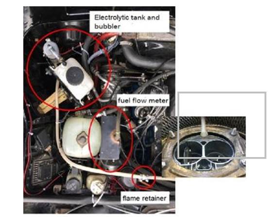
The line of HHO gas to engine has a bubbler, to retain some water and particulates of electrolyte, and a flame retainer. In the car body, the cell should be in a well-ventilated place, in a supportwith enough stiffness to avoid damage because of vibration, and where all hose connectionsare easy to assemble and check. Inside the engine compartment, below cover, are the rest of components: water tank, bubbler, flame retainer and hoses. Also is the flow meter, between gasoline tank and fuel pump.
Finally, in the dashboard is an interrupter to connect and disconnect the cell, according to the driver will. During the test, a digital ammeter controls the cell currents. The system is shown in figure 2, the output is connected inside the air filter.
The cell is bolted to a steel frame; below the front bumper. This location ensures enough fresh air, an easy access to cell connectors and revision of all cables, that were one of the most frequently cause of system malfunctioning.
The automobile is a VAZ 21074, with engine 2106. Some data about automobile are:
Totalmass: 1430kg
Tires: 165/80 R13
Inflation pressure:
Front wheels: 0.16 MPa or 1.6 kgf/cm2
Rear wheels: 0.19 MPa or 1.9 kgf/cm2
The car has an alternator with maximum current of 55 A (at 13 V and engine speed of 5000 rpm). Maximum engine speed is 13000 rpm, the battery is of 60 A-h. The carburetor is an emulsion type, with two barrels, descendent and with pneumatic driven throttle in secondary chamber.
The fuel deposit is pressure balanced, and possess a connection with carter after choke.In addition, has a pneumatic economizer, diaphragm acceleration pump, autonomous relent system, etc. Original main fuel jet diameter valve in first barrel is 1,12 mm; in the second barrel is 1,5 mm. The gasoline used is Premium type, 94 octane. The road selected for the test is a plane stretch of La Habana-Melena freeway. This section has no potholes, is in good conditions, and without trees in both sides. Weather conditions were checked at the beginning of each travel. Only when wind was below 1 m/sec, and a sunny day with no rain forecast, the test proceeded.
Two traffic signals at 1 km each to the other marked the test length. Each test was repeated three times in each direction. Before launching experiments, the car was inspected, including tires, oil level, steering system, brake system, cooling system, carburetor, etc., and at the very beginning of each travel, tires pressure was checked and corrected if necessary. In the first round of experiments, hydrogen did not produce any perceptible saving in fuel consumption. Following cell manufacturer recommendations, fuel jet diameter valves were then changed from 1, 12 to 1,07 in the primary chamber, and 1,50 to1,3 mm in the secondary chamber respectively for a second round. The car speed was 40, 60, 80 and 100 km/h. For 40 km/h the car was in 4th speed (direct 1:1), for the rest used the 5th (0,82 transmission relation, or multiplication).The fuel consumption meter is a Flowtronic 206,this device has a measurement range of 0,5 to 60 l/hour; capacity of 0 to 99,99 liters and precision of ±0,5 %. A third test was the measurement of fuel consumption and gas composition with the cell fed by an external battery and the vehicle stationary with original carburetor. In this test, both radiator fans were disconnected. An external fan simulates the airflow through radiator, assuring a stable water temperature of about 87°C. In this test, the exhaust gas composition is determined using a gas analyzer CAPELEC CAP3200-OPA.
RESULTS AND DISCUSSION
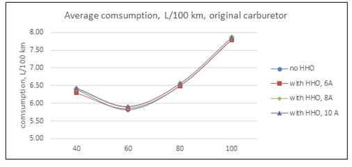
As was said, in the first round of experiments the car usedits standard carburetor. Results withdifferent cell currents are in Table 1 and Fig 3. HHO production in each case are 0,297 l/min with 6 A; 0,387 l/min with 8 A and 0,522 l/min with 10 A. Is necessary to point out that the bigger the current, the bigger the electrical load imposed to engine alternator.
Table 1 average consumption with original carburetor, L/100 km
| no HHO | with HHO | ||||||
|---|---|---|---|---|---|---|---|
| speed (km/h) | Reference | 6A | var (%) | 8A | var (%) | 10A | var (%) |
| 40 | 6.3867 | 6.2933 | 1.46 | 6.4033 | -0.26 | 6.4367 | -0.78 |
| 60 | 5.8200 | 5.8533 | -0.57 | 5.8883 | -1.17 | 5.9183 | -1.69 |
| 80 | 6.5017 | 6.4933 | 0.13 | 6.5533 | -0.79 | 6.5600 | -0.90 |
| 100 | 7.8150 | 7.7883 | 0.34 | 7.8583 | -0.55 | 7.8650 | -0.64 |
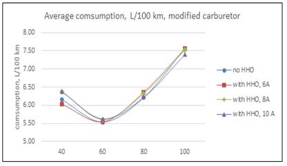
Results in the second test with modified carburetor are in Table 2 and Fig 4.
Table 2 average consumption with modified carburetor, L/100 km
| no HHO | with HHO | ||||||
|---|---|---|---|---|---|---|---|
| speed (km/h) | Reference | 6A | var (%) | 8A | var (%) | 10A | var (%) |
| 40 | 6.1533 | 6.0300 | 2.00 | 6.3800 | -3.68 | 6.3700 | -3.52 |
| 60 | 5.5383 | 5.5433 | -0.09 | 5.6100 | -1.29 | 5.6225 | -1.52 |
| 80 | 6.2200 | 6.3633 | -2.30 | 6.3250 | -1.69 | 6.2250 | -0.08 |
| 100 | 7.5667 | 7.5683 | -0.02 | 7.5250 | 0.55 | 7.4050 | 2.14 |
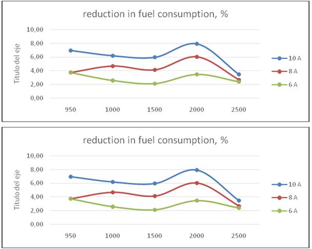
In the stationary test the engine has no load, the cell is fed by an external battery, the carburetor jet fuel were the originals: 1, 12 and 1,50 respectively. The engine works with water at 87° C, first, the engine consumption is measured without HHO supply, and later with same currents for the road test. The engine runs at different crankshaft speeds; the measuring time was 1 minute in all test and the cell works at 6 A, 8A and 10 A. Results are in Table 3 and Fig 5.
Table 3 fuel consumption in liters, and variation in %
| Engine speed, rpm | no HHO | 6A | % | 8A | % | 10A | % |
|---|---|---|---|---|---|---|---|
| 950 | 0,0188 | 0,0181 | 3,72 | 0,0181 | 3,72 | 0,0174 | 6,95 |
| 1000 | 0,0194 | 0,0189 | 2,58 | 0,0184 | 4,66 | 0,0182 | 6,19 |
| 1500 | 0,0235 | 0,023 | 2,13 | 0,02263 | 4,11 | 0,0221 | 5,96 |
| 2000 | 0,0317 | 0,0306 | 3,47 | 0,0297 | 6,01 | 0,0291 | 7,91 |
| 2500 | 0,0377 | 0,0368 | 2,39 | 0,0366 | 2,66 | 0,0363 | 3,46 |
Is necessary to remember how a carburetor engine work: air pass through carburetor venturi tube and creates a vacuum, gasoline flows ought to pressure differential, and is mixed with air before entering in cylinders. If engine speed increase, the pressure is lower and gasoline flow is larger. The air to fuel relation is around the stequiometric in all regimes. The engine control is through mass flow, which depends mainly of engine speed. As is evident from Fig 3, the best cell configuration is with 6 A, consumption improves in 1,46% for a 40 km/h speed, nevertheless, the hydrogen effect at 80 and 100 km/h is contemptible. With the cell consuming 8 A and 10 A, the effect is completely adverse.
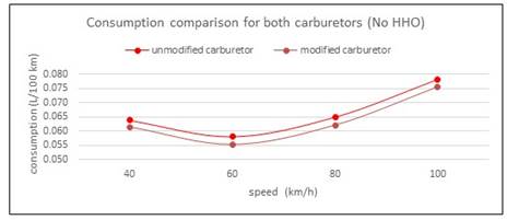
This result take place because as long as the cell current decreases, the power taken from the engine is less important, and the effect of HHO is more visible. When the current cell increases, the HHO has no effect, because the extra power demanded by the cell from alternator comes from gasoline and speed engine reduce slightly, consequently the air-fuel charge is also reduced. Therefore, the effect of the electrolytic cell is negative. In the second round of test with modified carburetor, results are shown in Table 2 and Fig 4. First, notice the consumption reduction respect to original carburetor (second column in Table 1 and Table 2.Now, the hydrogen added has a positive effect in 40 km/h with 6A and in 100 km/h with 8 and 10 A, being the last the bigger. The same facts signaled in the former paragraph are present. In the first case, this is because the low energy demanded by the cell with a current of 6 A. At high speed, the engine should run faster, the valves have less time to open and close, and as a result, the volumetric efficiency decreases slightly. Nevertheless, HHO gas contains an amount of oxygen, and this, together with Hydrogen contributes to a good combustion process. These results are in line with [12]. In Table 1, is also visible the trend to a minor increment in fuel consumption at 100 km/h, even with the cell at 10 A. Is very interesting to compare consumptions between carburetors. All cell manufactures recommend to reduce the diameter of jet fuel valves, because with HHO it will not be necessary the same gasoline flow. In the Fig. 6, is easily visible the positive effect of this reduction, with a fuel saving of 3,81% as average. Moreover, after modification there was no perceptible variation in vehicle dynamic. This open the question about the facts argued by manufacturers respect to fuel savings in carburetor engines are true, or are because the modifications in carburetor and way of driving.
Despite the importance of engine fuel consumption, it is necessary to analyze the car movement efficiency: the engine is only one of several contributors in the vehicle behavior.
The vehicle movement efficiency is the relation between energy (work) used to move the vehicle Emov and the energy supplied by fuel for the same objective Efuel. equations (2).
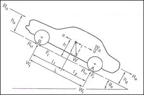
Several forces act over a vehicle in movement. Some of them are resistance forces, and only the force applied by the road to traction wheels is a tractive force, Fig 7.
In Fig 7, the movement is from right to left, climbing a slope with angle θ. This forces are in the longitudinal direction, the aerodynamic resistance Ra, rolling resistance in front and rear tires Rrf, and Rrr, drawbar load Rd, gravity resistance Rg, (W sin θ,), and tractive forces of the front and rear tires Ff andFr,. For a rear-wheel-drive vehicle, Ff, = 0, whereas for a front-wheel vehicle,Fr, = 0. In a 4-wheels driven vehicle, both have value. In vertical directions are Wf and Wr, road reactions in front and rear axles, dependents of weight distribution. In the figure are some dimensions necessary for calculus.
The equation of movement is: equations (3).
m |
vehicle mass, kg |
w |
vehicle weight, N |
g |
gravity acceleration, m/s2 |
a |
vehicle acceleration, m/s2 |
Ff |
tractive force, N |
Rrf, Rrr |
rolling resistance force in front and rear wheels, N |
Ra |
aerodynamic resistance, N |
Rd |
trailer resistance, N |
Rg |
resistance by weight, N |
Considering 𝐹𝑡=𝐹𝑓+𝐹𝑟,where𝐹𝑡 is total tractive force and 𝑅𝑟=𝑅𝑟𝑓+𝑅𝑟𝑟, where 𝑅𝑟 is the total rolling resistance force, equations (3).is rewritten as: equations (4).
Moreover, during test speed is constant, so acceleration a is 0, there is no trailer, so Rd is 0 and Rg is also null, because the slope θ is 0°. Finally, for the tractive force: equations (5).
For the aerodynamic resistance Ra:: equations (6).
Here:
ρ |
Air density; 1,1614 kg/m3 |
CD |
Aerodynamic resistance coefficient; 0,387 |
Af |
Vehicle frontal effective area, (0,79÷0.84 total frontal area); 1,59 m2 |
Vf |
Relative vehicle speed respect air speed; equal to vehicle speed2, m/s |
For the rolling resistance Rr : equations (7).
where fr is the rolling resistance coefficient.This coefficient depends of tire type, inflation pressure, vehicle speed, etc. Its empirical value for a radial tire on a passenger car up the speed of100 km/h is: equations (8).
Finally: equations (9).
However, considering that the slope is zero. Equations (10).
The vehicle massm is 1030 kg from the vehicle and 180 kg ought to three passengers, for a total of 1210 kg, the total tractive force will be: equations (11).
Results for the four speeds in road test are in Table 4. These forces are constant and remain the same in all test.
Table 4 Forces and energy in road test.
| speed km/h | speed m/s | Frr | Rr | Ra | Ft | Emov, kJ, in 100 km |
|---|---|---|---|---|---|---|
| 40 | 11.11 | 0.0159 | 189.08 | 44.11 | 233.19 | 23319.13 |
| 60 | 16.67 | 0.0169 | 201.95 | 99.26 | 301.21 | 30120.85 |
| 80 | 22.22 | 0.0185 | 219.98 | 176.46 | 396.43 | 39643.26 |
| 100 | 27.78 | 0.0204 | 243.15 | 275.71 | 518.86 | 51886.36 |
The work (energy) done by tractive force is: equations (12).
In equations (12), displacement ΔS is 100 km, result are in last column in Table 4. The energy delivered by fuel is: equations (13).
Where:
SFC |
Specific fuel consumption, L/100 km ,Table 1 |
ρfuel |
Fuel density, 760 kg/m3 |
HLV |
Heat Lower Value of gasoline, 43 900 kJ/kg |
Efficiency as per equations (2), and its relation to efficiency without HHO is in Table 5, using data with original carburetor.
Table 5 Efficiency on car movement and variation respect no HHO as reference.
| speed km/h | 0A | 6A | % | 8A | % | 10A | % |
|---|---|---|---|---|---|---|---|
| 40 | 10,94 | 11,11 | 0,02 | 10,92 | 0,00 | 10,85 | -0,01 |
| 60 | 15,51 | 15,43 | -0,01 | 15,33 | -0,01 | 15,25 | -0,02 |
| 80 | 18,28 | 18,31 | 0,00 | 18,14 | -0,01 | 18,11 | -0,01 |
| 100 | 19,89 | 19,96 | 0,00 | 19,79 | -0,01 | 19,76 | -0,01 |
Only at speed of 40 km/h and cell at 6A exist a very low increment in efficiency or positive effect of HHO, and even at 60 km/h there is a decrement. This result shows that the use of an electrolytic cell has no positive effect in a carburetor engine, more; the effect is negative or even null. This result is related with the carburetor function: any light reduction in engine speed (because the alternator applies an extra load feeding the electrolytic cell) reduces airflow and gasoline, and power delivered. The amount of HHO added is not enough to balance the whole process, even despite the better combustion that should occurs when hydrogen is present. The stationary test results are in Table 3 and figures. As can be seen, in all regimes exist an important saving. The higher is for a 10 A current, a logical result taking into account that in regime, the amount of HHO is the greatest and the cell is taking no energy from the engine. The fuel saved represents energy, as can be seen in Table 6.The energy provided by HHO is 0,54 kJ, 0,72 kJ and 0,901 kJ for 6, 8 and 10 A; these values are negligible respect the energy represented by the fuel saved. Is evident that the saving are related for the better combustion in presence of HHO and not because its amount.
Table 6 fuel saved in L and energy saved in fuel, kJ
| rpm | 6 A | kJ fuel | 8 A | kJ fuel | 10 A | kJ fuel |
|---|---|---|---|---|---|---|
| 950 | 0,0007 | 23,35 | 0,0007 | 23,35 | 0,0013 | 43,37 |
| 1000 | 0,0005 | 16,68 | 0,0009 | 30,03 | 0,0012 | 40,04 |
| 1500 | 0,0005 | 16,68 | 0,00097 | 32,36 | 0,0014 | 46,71 |
| 2000 | 0,0011 | 36,70 | 0,0019 | 63,39 | 0,0025 | 83,41 |
| 2500 | 0,0009 | 30,03 | 0,001 | 33,36 | 0,0013 | 43,37 |
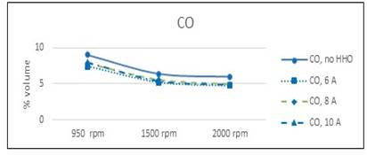
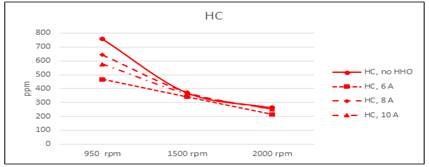
However, the cell efficiency is included in the process, so this does not represent a real saving when the cell is fed by the own engine.The analysis of escape gas composition made at 950, 1500 and 2000 rpm shows a reduction in CO and unburned HC in all regimes figure 8 and figure 9. The reduction in CO is almost the same for all speed, because the more efficient combustion in presence of HHO. Regarding unburned HC, is more significant in 950 rpm, when the mix is leaner. At this speed are more possible fails in gasoline ignition, but the ignition energy of hydrogen is about 10% of gasoline, and ignite more easily, burning the remainder of gas in cylinder. This result underline the positive effect of hydrogen in burning a lean mixture of gasoline and air.
CONCLUSIONS
The presence of HHO in gasoline combustion is beneficial for a better use of the energy contained in fuel, but as long as the electrolytic cell represent a significant load to engine, this not mean real fuel savings.
The use of an electrolytic cell for HHO production in a carburetor engine does not implies a reduction in fuel consumption.
The additional electric load the electrolytic cell imposes to engine alternator trends to reduce engine speed and consequently gas mass entering into engine and power delivered, and the amount of hydrogen supplied does not full fill this reduction.
The reduction in jet fuel valves size recommended by cell manufacturers and the saving in fuel consumption that result might be misunderstood as a positive effect of HHO.
Emissions of CO and unburned HC is lower when HHO participates in combustion, ought to its greater flammability and minor ignition energy.
In gasoline engines with direct fuel injection, air and fuel are not so closely linked. In this case is possible to obtain a positive result with the use of electrolytic cell. This have to be studied in detail, considering the ECU system.


