


 Servicios personalizados
 Inglés (pdf)
 Articulo en XML
 Referencias del artículo
 Enviar articulo por email
 Citado por SciELO
  Similares en
SciELO
Similares en
SciELO 
 Permalink
Introduction
There are several works related to the study of the behavior of AGESC (all-glass evacuated tube solar collectors) working in a thermosiphon regime and in a forced regime where both natural and forced convection are combined. A review of the works developed on this subject leads to dividing them into works related to natural convection, works related to forced flow, works related to both natural and forced convection, simulation works and experimental works.
Among the works related to natural convection is the one carried out in [1] where a study of the behavior of a solar collector of evacuated tubes all glass is carried out, for different inclination angles which coincide for medium and high latitude (> = 20º). In [2] the work presented introduces an investigation using computational fluid dynamics for the thermal performance of the single ended all water ETSC of one tube. Also in the work [3] a study is carried out on the effect of the angle of inclination on the behavior of a collector working with water where the angle of inclination was varied between 30 and 45 degrees. Another work dealing with all glass collector is [4] where the thermal performance and internal flow of horizontal double-row water-in-glass evacuated solar collectors with different declination angles are investigated. The authors concluded that the instantaneous efficiency of horizontal double-row ETC increases with the increase of declination angle, while heat loss coefficient is not significant change. In order to increase the performance of the all glass collector evacuated solar collectors in [5] the authors indicate that, the twist tape inserts makes the mixture of the water near the top and bottom half of the tube more intense, destroys the original orderly flow and generates more eddy, which leads to a higher dissipation of mechanical energy and thus reduces velocity magnitude, at the same time, makes the temperature field more uniform. In [6] results show a minimum heat transfer between the solar water heater and the ambient during the night. Reduction in the outlet temperature in the morning is significantly influenced by the mixing of the hot water above the tube opening and the cold water below during the night. The research developed in [7] was conducted to modelling simulation on a single vacuum tube collector to obtain on the effect of parameters on the thermal efficiency of evacuated tube solar collector.
From the previous analysis it can be seen that many aspects of the thermohydraulic behavior of the collectors are still being investigated and that these investigations are also highly framed for medium and high latitudes (>=20º). Another aspect seen in the analysis is that the models that have been established take into account the equality of flow area for the hot fluid and for the cold fluid.
Therefore, the objective of the present work is the modeling of a solar collector with evacuated tubes all glass where the non-uniformity of the flow area of the hot fluid and the cold fluid is taken into account, as well as the angle of inclination of the collector less than 20º.
Methods
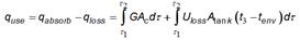
Figure 1 shows the diagram of the heater to be modeled. For the modeling, the thermal behavior of the collector is considered from an energy balance where the gain and loss of energy in it are considered.

From the energy and flow conservation equations, the flow caused by natural circulation (ṁ) through the evacuated tube in a solar heater can be determined from the energy collected in the tube, the initial temperature and the final temperature in the monitoring time [1], equation (1):
 (1)
(1)
Where, equation (2):
 (2)
(2)
Where G is the incident radiation on the collector, Ac is the collector catchment area, m is the mass of the water in the tube (2,5 kg), the subscripts 1 and 2 indicate the start and end of monitoring, t3 is the temperature at the top of the tube and tenv room temperature.
The equation for the calculation of the thermosiphon flow is based on considering the equality of flow area for both the hot fluid and the cold fluid. In [1] the development of the heat transfer process was carried out in an inclined tube heated from its lower end and with adiabatic sides. In this study, equality of flow section was also considered for hot fluid and cold fluid.
In this work, unlike that of [1] the model is developed for the case in which constant heat from the sun is received through the sides of the tube and also the hot and cold fluids do not circulate in the same flow section. Figure 2 shows the control volume of the collector tube with inclination ( with respect to the vertical and the balance of force and energy.
The assumptions made in this analysis are as follows:
Developed laminar flow and steady state.
Newtonian Flow.
Constant properties except density.
The lower end of the tube is adiabatic
The pressure gradient of hot fluid and cold fluid are equal:

If they were different, then there would be flow in the transverse direction.
Heat conduction in the direction of fluid movement is neglected.
For the differential of the tube dx the hot water increases its temperature in t hot + dt hot and the cold water increases its temperature in t cold + dt cold .Heat transfer occurs between both currents.
The energy balance for each current is, see figure 2:

For the hot stream
 (3)
(3)
For the cold stream
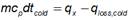 (4)
(4)
In the previous equations q, qx and qloss are the incident energy at the top of the tube, the heat exchanged between the streams and the heat lost to the outside by each stream, respectively.
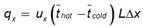
The calculation of the heat absorbed and the heat exchanged between the currents is determined from equations (5) and (6)
 (5)
(5)
 (6)
(6)
Where  and
and  are the average temperatures of each current and L is the value of the contact chord between the hot and cold current and r is the radio of the circle, figure 3.

The heat loss is determined through equations (7) and (8)
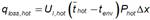 (7)
(7)
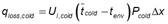 (8)
(8)
Where P hot and P cold are the perimeter covered by the hot and cold fluid respectively, figure 3.
For the analysis, the same value of the heat transfer coefficient of losses to the environment was taken, U l for both currents, that is U l,hot =U l,cold =U l
The term U x is the heat transfer coefficient between the hot and cold streams and is determined as a function of the film heat transfer coefficients h hot and h cold the hot and cold stream respectively.
For the analysis of the thermosiphon flow that is established in the tube, it is necessary to resort to the equation of momentum which is based on Newton's 2nd law. Figure 2 shows the forces acting on the control volume of the hot fluid and the cold fluid. From the balance of forces and not considering change in momentum in the x direction, equation (9) results.
 (9)
(9)
Where f hot and f cold are the flow area of the hot and cold fluid respectively and they are calculated by equations (12) and (13) respectively:
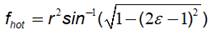 (10)
(10)
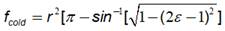 (11)
(11)
 and
and  are the total wet perimeter of the hot and cold fluid respectively, which are determined according to figure 3:
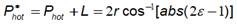 (12)
(12)
 (13)
(13)
Where ε is the relationship between the part covered by the hot fluid and the part covered by the cold fluid,

In equation (9)( w,hot and ( w,cold is friction. This can be determined according to [8], by the equation:

For the case of laminar flow, the average friction factor ( is determined as a function of the Reynolds number according to the equation, where C it is a constant:

The characteristic dimension in the Reynolds number is the hydraulic diameter determined according to the equations [8] [9] by the equation:

Working with the equations of (, ( and d h friction is obtained through equation (14). In this equation P ( , f, ν, and m are the wetted perimeter, flow area, kinematic viscosity, and flow of the hot or cold fluid.
 (14)
(14)
The temperature difference  in equation (9) can be determined from equations (3) and (8), resulting in the equation
 (15)
(15)
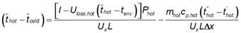
Substituting equation (15) in equation (9) and considering equation (14) we arrive at equation (16) for the determination of the fluid flow.
 (16)
(16)Equation (16) gives the relationship between the flux created and the incident radiation. One of the simplifications for the development of this equation is that the flow regime is laminar and developed. For this case, the value of the film heat transfer coefficients are determined for a constant Nusselt value (Nu = 4,36), under a constant heat contour condition [9]. Furthermore, considering that both film coefficients are similar in magnitude, then the global coefficient between both currents can be evaluated with equation (17)
 (17)
(17)The loss coefficient of a vacuum tube can be taken from a value of 0.85 W/m2K, a characteristic value for these tubes [10].
Results and Discussion
Under the considerations made, figures 4 and 5 show the result of the application of equation (16) for the calculation of the thermosiphon flow.
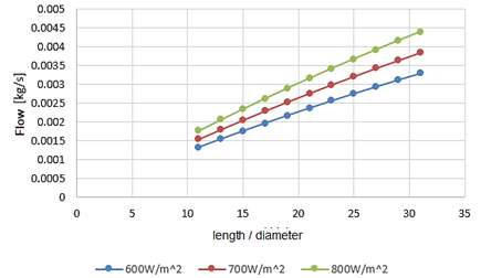

For the analysis of the behavior of the thermosiphon flow, a program was made in Matlab 2013b. Figure 4 shows the growth of the thermosiphon flux as the incident solar radiation increases and the length / diameter ratio of the tube increases. Figure 5 shows the growth of the flux with respect to the incident radiation and the slope (the angle between the plane of the evacuate tube and the horizontal). It is observed that when increasing the angle for small values of this (< 20o), the variation of the flux is more notable than for larger angles.
The variation of the thermosiphon flow shows a direct dependence on the ratio of the length to diameter of the absorber tube and on the incident radiation (absorbed) in the collecting tube. This corroborates the increase in useful energy as the catchment area increases for a given loss coefficient.
The results of this equation were compared to the results of the works of [11] obtaining good correspondence for values of relation of areas ε = 0,5.
Conclusions
In this work, it was possible to determine the liquid flow that occurs in a solar collector with all glass evacuated tube working in thermosiphon regimen. This flow was obtained as a function of the angle of inclination and the length/diameter ratio of the tube.
The non-uniformity of the radiation absorbed by the tube was taken into account when considering the solar heat only in the upper part of the tube.

