Mi SciELO
Servicios Personalizados
Revista
Articulo
Indicadores
-
 Citado por SciELO
Links relacionados
-
 Similares en
SciELO
Compartir
Ingeniería Energética
versión On-line ISSN 1815-5901
Energética vol.35 no.3 La Habana sep.-dic. 2014
APLICACIÓN DE LA COMPUTACIÓN
Reassessment and proposal of synchronization scheme for grid connected static converters under disturbed utility
Nueva evaluación y propuesta de un esquema de sincronización para la conexión a la red de convertidores estáticos de potencia en presencia de perturbaciones de la red eléctrica
Dr. Giuseppe BujaI, MSc. Osley LópezII
I Laboratory of Electric Systems for Automation and Automotive, University of Padova, Padova, Italy.
II Faculty of Electrical, "Jose Antonio Echeverria" Higher Polytechnic Institute (ISPJAE), Havana, Cuba.
ABSTRACT
The paper starts by casting new light to the existing Phase Lock Loop (PLL) schemes used to synchronize the static converters with the grid under utility disturbances. Two approaches are pursued to detect the fundamental harmonic of the positive-sequence component of the grid voltages in presence of the disturbances. Arithmetical approaches improve the operation of the basic PLL circuit by making robust the PLL algorithm. Structural approaches improve the operation of the basic PLL circuit by adding a block intended to cope with the disturbances. This paper considers the structural approach and shows that it works by either post processing the detected grid quantities or preprocessing the grid voltages. Afterwards, the paper proposes an improved PLL scheme termed as double processing (DP) PLL scheme since it includes preprocessing and post processing functionalities. By properly designing the scheme parameters, it is proved that the proposed scheme exhibits superior robustness against the utility disturbances.
Key words: active compensators, distributed generation, grid synchronization schemes, grid-connected three-phase converters.
RESUMEN
El artículo realiza una descripción de los principales esquemas de lazos de enganche de fases (PLL según sus siglas en inglés) usados para sincronizar convertidores estáticos de potencia en una red eléctrica en presencia de perturbaciones eléctricas. Se profundiza en dos esquemas principales para la detección de la componente de secuencia positiva del armónico fundamental. Un enfoque aritmético mejora la operación del esquema PLL básico haciéndolo más robusto. Un enfoque estructural mejora la operación del esquema PLL básico por la acción de un bloque auxiliar que elimina el efecto perturbador presente en la red eléctrica. Este artículo considera el enfoque estructural y muestra cómo funciona tanto la detención de las variables eléctricas post procesadas o el preprocesamiento de la tensión de la red. Posteriormente se propone un esquema de PLL mejorado llamado lazo de enganche de fase con doble procesamiento. Se demostró mediante simulación la superioridad del esquema propuesto ante sus similares aún en condiciones perturbadas de la red eléctrica.
Palabras clave: compensadores activos, generación distribuida, esquemas de sincronización, convertidores trifásicos conectados a la red.
INTRODUCTION
The proliferation of power electronics equipment and conventional electric loads experimented in the last 30 year has had the twofold impact of polluting the grid and making it weak. In parallel, an increasing number of apparatuses has been connected to the grid through static converters for either conditioning the power flow in the line or delivering power to the utility [1]. Examples of such apparatuses are the active filters and the distributed generators using renewable energy sources like photovoltaic and wind sources. These apparatuses require fast and accurate tracking of the three-phase system of the fundamental positive-sequence harmonics of the grid voltages to synchronize the static converters. While the task of detecting the required grid quantities is simple for sinusoidal, balanced line voltages, it becomes somewhat complicate when the line voltages are subjected to disturbances such as distortion caused by non-linear loads and unbalance caused by uneven single-phase loads or, at worst, by short-circuit. A multiplicity of schemes has been developed to detect the required grid quantities. They can be broadly classified into two groups depending on whether they use an open-loop or a closed-loop method to execute the detection [2]. The schemes using the closed-loop method exploit the PLL principle and are more robust against grid disturbances. Therefore they are considered hereafter. The literature divides the existing PLL schemes into two categories. One category is based on a PLL circuit that operates in the stationary reference frame (StPLL) whilst the other one is based on a PLL circuit that operates in a synchronous reference frame (SyPLL).The two PLL circuits are derived respectively from the instantaneous p-q powers theory [3] and the d,q transformation theory of a three-phase system of variables [4]. They are accurate in detecting the required grid quantities under sinusoidal, balanced operation of the utility as well as under small disturbances of the grid voltages while are sensitive to medium-large disturbances. To overcome this shortcoming, improved PLL schemes have been built up around the two PLL circuits [5-12]. It is shown in Section II that the two PLL circuits are equivalent; hence the classification of the improved PLL schemes into two categories depending on the PLL circuit that they use has no reasons to exist.
Further to this result, the improved PLL schemes are here classified in a different way that is correlated to the approaches pursued to detect the required grid quantities in presence of disturbances. The two approaches are termed as arithmetical and structural.
The arithmetical approach enforces the algorithm utilized by the PLL circuit to detect the grid quantities by making it insensitive to the grid disturbances. In [5] the PLL circuit is endowed with both a feed-forward action to guarantee high dynamic performance and a reworked feedback action to force the calculation error of the grid angle to zero. In [6] a filtered-sequence PLL scheme is arranged that includes a moving average filter to completely eliminate any harmonic multiple of the frequency for which it is designed; the scheme, moreover, includes an algorithm that makes the grid frequency detection adaptive. In [7] a PLL scheme is developed that synthesizes a unit voltage space vector by help of a modified synchronous reference frame; the PLL scheme is implemented by means of a coulomb oscillator formed by an IIR filter and a sine-cosine lookup table, and is endowed with a shift pointer that represents a number of samples proportional to the grid angle. This PLL scheme runs without any PI regulator, thus increasing the calculation speed of the grid quantities.
The structural approach supplements the PLL circuit with an additional block that copes with the disturbances [8-12]. The additional block is inserted either after the PLL circuit or before it; in the first case the additional block works by post processing the detected grid quantities whilst in the second case it works by preprocessing the grid voltages. The relevant PLL schemes are discussed in Section III.
The paper, after dealing with the two PLL circuits and the structural PLL schemes, proposes in Section IV an improved PLL scheme of structural type that is extremely robust against the grid voltage disturbances because it merges the preprocessing and post processing blocks into a single PLL structural scheme and, by exploiting the specific capabilities of the blocks, permits an effective design of the parameters of the scheme. The oscillograms of some synchronization tests carried out on the proposed PLL scheme under heavy grid disturbances are reported in Section V and demonstrate its superior performance compared to the existing improved PLL schemes. Section VI closes the paper.
Basic PLL circuits
A. PREMISES
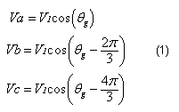
Three-phase grid systems with no neutral wire are considered. The grid voltages Va, Vb and Vc when sinusoidal and balanced can be equations as (1)
where θg is the grid angle.
Grid voltages can be distorted and unbalanced. Distortion is due to odd, non-triple voltage harmonics. Their order is given by n=6k±1 with k integer, and their sequence is positive for the order 6k+1 and negative for the order 6k-1. Unbalance is due to negative-sequence voltage component at the fundamental frequency. Under these disturbances, the grid voltages in equations (1) become equations (2)
Whether clean or not, the grid voltages can be univocally represented in the α,β stationary reference frame by applying the following power-invariant transformation equations (3):
After extension, the matrix in equations (3) is invertible and the three-phase grid voltages can be readily found from their α,β expressions. Then only transformed grid voltages will be take into account. The grid voltages can be also univocally represented in the d,q synchronous reference frame rotating at the grid angular frequency. By selecting the grid angle as the current angular position of the rotating d,q synchronous reference frame, the d,q expressions of the grid voltages as a function of the α,β counterparts are equations (4).
To synchronize the static converters to the grid, it is necessary to detect the grid angle alternative, its sine and cosine functions. These functions represent the α,β templates of the required grid voltages, i.e. the α,β unity-magnitude quantities reproducing the fundamental positive-sequence harmonic of the grid voltages. They are given by equations (5)
Besides θg, some synchronization circuits detect the magnitude V1+ of the fundamental positive-sequence harmonic of the grid voltages, shortly termed as grid magnitude. From θg and V1+, the required grid voltages are equations (6):
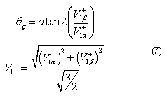
and vice versa, from V1α+ and V1β+, the grid angle and the grid magnitude are computed as equations (7):
Where: atan2 stands for the arctangent function calculated over the four quadrants. Incidentally, the auxiliary detection of V1+ is of interest for certain applications of the grid-connected static converters, f.i. to detect the active power flowed by the fundamental positive-sequence harmonics of the grid voltages.
B. STPLL
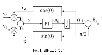
As anticipated in Section I, the StPLL circuit is derived from the instantaneous p-q power theory. The circuit has the block diagram of figure 1; its inputs and output are the α,β grid voltages and the grid angle, respectively.
The circuit utilizes some computations to detect the grid angle. Starting from the estimated phase angle θ, the computations are as follows: i) calculation of the orthogonal unity currents i"α ,i"β by sine and cosine functions of θ; the currents are internal-generated quantities that do not have any relation with the line currents, ii) calculation of the so-called fictitious instantaneous active power equations (8):
Where: Vα and Vβ are the grid voltages. This power is called fictitious since i"α ,i"β are not the line currents, iii) entering of p" into the PI regulator that adjusts its output until the PLL circuit reaches a stable operating point; the output of the PI regulator is denoted with ωg as it represents an estimate of the grid angular frequency, iv) integration of ωg to obtain θ, and v) calculation of θg.
Let us assume that the grid voltages are sinusoidal and balanced as expressed by equations (1). The StPLL circuit reaches a stable operating point when the input p" to the PI regulator is steady at zero. When this occurs, ωg is equals to the grid angular frequency and the space vector i"αβ of the currents i"α ,i"β is orthogonal to the space vector Vαβ of the grid voltages Vα,Vβ. The condition p"=0 is met for two values of θ, i.e. for , but it is steadily maintained only when i"αβ is leading Vαβ, i.e. for . Then the grid angle is calculated as equations (9).
When the grid voltages are distorted or unbalanced, the quantity p" contains harmonics that are not fully attenuated by the PI regulator. Therefore the detected grid angle is affected by oscillations that impair its accuracy.
C. SYPLL
As anticipated in Section I, the SyPLL circuit is derived from the d,q transformation theory of a three-phase system of variables. The circuit has the block diagram of figure 2; its inputs and outputs are the α,β grid voltages, and the grid angle and magnitude, respectively.
The circuit utilizes some computations to detect the two grid quantities. Starting from the estimated grid angle θg, the computations are as follows: i) calculation of the grid voltage Vq using θg as the current angular position of the rotating d,q synchronous reference frame, ii) entering of Vq into the PI regulator that adjusts its output until the PLL circuit reaches a stable operating point; the output of the PI regulator is still denoted with ωg as it represents an estimate of the grid angular frequency, and iii) integration of ωg to obtain θg, and iv), if requested, calculation of the grid voltage Vd to detect the grid magnitude as well.
Let us assume that the grid voltages are sinusoidal and balanced. The SyPLL circuit reaches a stable operating point when the input Vq to the PI regulator is steady at zero. When this occurs, the space vector Vdq of the grid voltages Vd, Vq is aligned along the axis d of the d,q reference frame and the current angular position of the rotating d,q synchronous reference frame is just equal to the grid angle θg. Under this condition, it comes out from equations (4) that the term Vd gives the magnitude of the grid voltages. Like StPLL, the SyPLL circuit suffers from grid voltage distortion and unbalance.
D. PLL CIRCUIT EQUIVALENCE
By substituting equations (9) into equations (8) and by comparing the resulting expression with that one of Vq obtained by equations (4), it can be easily realized that the two expressions are equal, evidencing the fact that the two PLL circuits utilize the same quantity for the synchronization process. Therefore, hereafter the two PLL circuits are not more distinguished.
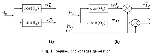
Manipulation of θg by equations (5) gives the templates of the required grid voltages, as drawn in figure 3(a). If V1+ is also available, manipulation of both θg and V1+ by equations (6) gives the required grid voltages, as drawn in figure 3(b).
Structural-improved PLL schemes
To comply with the disturbances in the grid voltages, the detection performance of the PLL circuit is improved by supplementing it with an additional block. If inserted after the PLL circuit, the additional block postprocesses the grid quantities detected by the PLL circuit with the end of removing the effects of the disturbances from them. If inserted before the PLL, the additional block preprocesses the grid voltages with the end of extracting the fundamental harmonic of the positive-sequence component of the grid voltages so as to enter clean voltages into the PLL circuit. From the literature, it emerges that all the PLL schemes based on the StPLL circuit insert the additional block after the PLL circuit whilst the opposite occurs for all the PLL schemes based on the SyPLL circuit [8, 11]. According to the findings of Section II, there is no any mandatory place of insertion of the additional block related to the PLL circuit and, indeed, a recent paper has suggested the insertion of the additional block before the StPLL circuit [12].
A. Post processing block
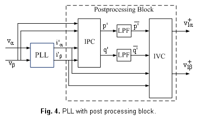
The improved PLL schemes with post processing block have the diagram of figure 4. Inputs to the additional block are the grid voltages and the unity currents i'α ,i'β; the latter ones are calculated by cascading the PLL circuit with the voltage template generation scheme in figure 3(a) and by assigning the role of currents to the outputted voltage templates.
The additional block works in three stages. The first stage consists of an instantaneous power calculator (IPC) that determines the instantaneous active and imaginary powers p' and q' produced by the inputted voltages and currents; the powers p' and q' are again fictitious quantities since the currents i'α ,i'β are not the line currents. Harmonics and the negative-sequence component of the grid voltages give rise respectively to harmonics of order multiple of six and of second order in the powers p' and q'. The second stage removes these harmonics by passing each power term through a low-pass filter LPF. Then the quantities delivered by the LPFs represent the average terms
A critical design specification for the improved PLL schemes with post processing block is the bandwidth of LPFs that must be somewhat low because of the need of removing the second-order harmonic arisen from the negative-sequence component of the grid voltages. Meeting this request becomes a shortcoming for the schemes as they exhibit a delayed answer to changes in the grid voltages and are made prone to an inaccurate detection of the grid angle (and magnitude) because of the phase shift (and attenuation) introduced by the LPFs.
B. Preprocessing block
The improved PLL schemes with preprocessing block assign two tasks to the additional block, namely abating of the harmonics and extraction of the positive-sequence component of the grid voltages. The two tasks are executed by means of the three stages HF, PSE and QSG shown in the diagram of figure 5.
Inputs to the additional block are the grid voltages whilst its outputs are the fundamental positive-sequence harmonics of the grid voltages. A question could arise on the need of cascading the PLL circuit to the preprocessing block. Indeed, the preprocessing block delivers just the required grid voltages and an in-cascade manipulation of the quantities V1α+ to V1β+ outputted by the block by equations (7) would give directly the grid angle and magnitude. The motivation is the enhanced detection of the grid quantities provided by the PLL circuit because of the smoothing action carried out by the PI regulator and the integrator forming the PLL circuit.
Harmonic filtering
The stage HF abates the harmonics of the grid voltages by means of two filters, one for each grid voltage. A filter of the second order with a band-pass shape centered on the fundamental angular frequency is commonly used. The transfer function of the filter is equations (10):
Where: ω1 and k are the resonance angular frequency and the damping factor of the filter. Regarding ω1, its value must stay equal to the grid angular frequency ωg in order that the phase of the fundamental harmonic contained in the grid voltage is not altered by the filter. When the condition ω1= ωg is met, also the magnitude of the fundamental harmonic is not altered by the filter. As outlined in figure 5, the objective of keeping ω1= ωg is attained by tuning ω1 to the value of ωg detected by the PLL circuit. Parameter k, in turn, affects the bandwidth of the band-pass filter in the way that low values of k make the bandwidth narrow.
Positive-sequence extraction
The stage PSCE extracts the positive-sequence component of unbalanced grid voltages by help of the instantaneous symmetrical component (ISC) theory [13]. The processing defined by the ISC theory to execute this extraction is equations (11):
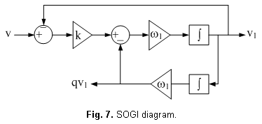
Where: q is a time-domain, phase-change operator that shifts the fundamental harmonic of -π/2 backward. A diagram of the PSCE stage is drawn in figure 6.
Although written for the fundamental harmonics Vα, Vβ, equations (10) applies with no loss of accuracy to distorted input voltages; it simply transfers the distortion of the input voltages to the output voltages. In order to reject the negative-sequence component in V1α, V1β, equations (11) requires only that the fundamental harmonic contained in the quantities qV1α, qV1β has the same magnitude and is lagging in quadrature with respect to the fundamental harmonic contained in V1α, V1β. The shift is obtained by the quadrature signal generation (QSG) stage explained below. Worth to note, processing in equations (11) does not have any dynamics and hence do not introduce any delay.
Quadrature signal generation
The stage QSG can be simply implemented by integrating each grid voltage outputted by the HF according to equations (12).
By equations (12), the output-to-input shift of is achieved irrespectively from the value of ω1 whilst tuning of ω1 to ωg is requested to keep unaltered the magnitude of the fundamental harmonic with respect to its magnitude in the grid voltages.
The drawback of equations (12) is the lack of any damping. This can be circumvented by putting together the transfer functions HF and QSG in a single transfer function denoted with FQ, i.e. equations (13)
Looking at equations (11) and equations (13), one observes that the two quantities V1 and qV1 can be obtained with only one stage by suitably arranging the transfer function in equations (11). The relevant stage is termed as second-order generalized integrator (SOGI) and has the diagram of figure 7
A critical design specification for the improved PLL schemes with preprocessing block is the bandwidth of the band-pass filters in the stage HF that must be somewhat small to provide a satisfactory attenuation of the grid voltage harmonics. Meeting this request becomes a shortcoming for the schemes as they exhibit a somewhat longer settling time and larger overshoot.
Improved scheme proposal
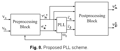
The post processing and preprocessing blocks used by the existing improved PLL schemes to improve the synchronization performance of the PLL circuit can be combined into a single arrangement to obtain a PLL scheme extremely robust against the grid voltage disturbances. The resulting scheme, drawn in figure 8, is inputted by Vα,Vβ, and outputs the required grid voltages outputs V1α+,V1β+. In the figure, the fundamental positive-sequence harmonics of the grid voltages as outputted by the preprocessing block are denoted with V'1α+,V'1β+.
The proposed PLL scheme enjoys two important features. The first feature is the possibility of charging each block with a different task, namely the preprocessing block with the rejection of the negative-sequence component of the grid voltages and a preliminary filtering of the grid voltage harmonics, and the post processing block with the final removal of the harmonics of the grid voltages from the detected grid quantities. This split of the tasks relies on i) the capability of the preprocessing block of executing a full rejection of the negative-sequence component of the grid voltages without demanding a narrow bandwidth for the band-pass filters in the stage HF, and ii) the capability of the post processing block of executing a large attenuation of the harmonics of the grid voltages without demanding a narrow bandwidth for the low-pass filters in the stage LPF because of two reasons: 1) the filters do not have to take care with the removal of the second-order harmonic produced by the negative-sequence component of the grid voltages, and 2) the filters have to cope with the harmonics of the fictitious instantaneous powers, the minimum order of which is 6, in contrast to the pass-band filters in the stage HF of the preprocessing block that have to cope with the harmonics of the grid voltages, the minimum order of which is 5. A second feature of the proposed PLL scheme is that the post processing block is entered by the quantities V'1α+,V'1β+. That, even if non-completely free from the harmonics of the grid voltages, are much less distorted, thus giving the scheme the opportunity of improving the detection accuracy. As a matter of fact, these features enable the proposed PLL scheme to exhibit superior grid-synchronization performance.
Computer-aided performance evaluation
Test description
The performance of the proposed PLL scheme in detecting the required grid quantities has been evaluated by computer-aided tests and compared to that one of the preprocessing and post processing improved PLL schemes. The results of two tests are here reported, whereby the 380 V, 50 Hz grid voltages have been disturbed by the sudden onset of disturbances: in test #1, a distortion due to 5th and 7th voltage harmonics of magnitude equal to 30 and 25 % of the fundamental harmonic, respectively; in test#2, an unbalance due to the short-circuit whilst the grid voltages are distorted as specified in test #1. Note that the magnitude of the harmonics in test #1 are much higher than those established by the standards for the tolerated grid voltage distortion [14], and that the composite condition in test #2 is a very heavy disturbance for the operation of a PLL scheme. Parameters of the schemes have been set in accordance with the design considerations stated in the previous Sections: bandwidth of the LPFs in the post processing PLL scheme has been set at 50Hz; factor k in the preprocessing PLL scheme has been set at 1/√2; bandwidth of the LPFs and factor k in the proposed PLL scheme have been set at 150 Hz and at 1, respectively.
A. Results
The results of test #1 are reported in figures 9(a)-(d) and those of test #2 in figures 10(a)-(d); onset of the disturbances in both the tests takes place at 0.04 s. Figures 9(a) and 10(a) give the waveforms of the grid voltages during the two tests. Figures 9(b)-(d) and 10(b)-(d) include three oscillograms each, where the oscillogram on the right-hand side refers to the post processing PLL scheme, the oscillogram at the center to the preprocessing PLL scheme and the oscillogram on the left hand-side to the proposed PLL scheme. In particular, figures 9(b) and 10(b) give the detected grid angle, figures 9(c) and 10(c) the error in the detected grid angle, and figures 9(d) and 10(d) the grid magnitude. Grid angle and magnitude have been plotted in place of the outputs V'1α+,V'1β+ of the scheme for the reader to better appreciate the dynamics of the detected grid quantities. They have been computed by means of equations (7).
Figures 9(a)-(d) show that all the schemes detect the grid quantities exactly when the grid voltages are sinusoidal and balanced. When the grid voltages become distorted, the detected grid quantities undergo a transient the dynamics of which do not differ too much for the post processing and preprocessing PLL schemes. Both transient and steady-state behavior is affected from superimposed high-amplitude oscillations, being much higher for the post processing PLL scheme. The proposed PLL scheme, instead, reacts quicker to the distortion and, by greatly reducing the oscillations, is able to execute a much more accurate detection.
Figures 10(a)-(d) starts from the steady-state detection achieved in test #1 and shows the transient in the detected grid quantities produced by the short-circuit of a grid phase. The effectiveness of the three PLL schemes are somewhat similar to that encountered for test #1, with high-amplitude oscillations plaguing the detection of the grid quantities from the post processing and preprocessing PLL schemes (being much higher for the post processing scheme) and, in contrast, with a smoother detection executed by the proposed PLL scheme. Regarding the grid magnitude, it can be noted that, under short-circuit, the magnitude of the fundamental positive-sequence harmonic of the grid voltages reduces to about two third of the value prior to short-circuit.
From the previous tests, it clearly emerges the superior performance of the proposed PLL scheme in detecting the grid quantities even in the presence of heavy disturbances in the grid voltages. Particularly under a grid short-circuit, the proposed PLL scheme tracks with accuracy the grid angle and is not affected by negligible oscillation.
CONCLUSIONS
The paper has dealt with the PLL schemes used to synchronize the three-phase static converters to the grid under a disturbed utility. After demonstrating the equivalence of the stationary and synchronous PLL circuits and classifying the improved PLL schemes as arithmetical and structural according to the approach used to cope with the grid voltages disturbances, the paper has discussed the structural PLL schemes and has shown that they make accurate the detection in two ways, namely either post processing the detected grid quantities or preprocessing the grid voltages. Afterwards, the paper has proposed an improved PLL scheme that exploits the capabilities of both the post processing and preprocessing blocks to provide an accurate and fast detection of the required grid quantities even under heavily disturbed voltages.
REFERENCES
1. TEODORESCU, R.; et al., "Grid Converters for Photovoltaic and Wind Power Systems". Chichester, UK: John Wiley & Sons, 2011, ISBN: 978-0-470-05751-3.
2. KARIMI-GHARTEMANI, M.; IRAVANI, M.R., "A Method for Synchronization of Power Electronic Converters in Polluted and Variable-Frequency Environments". IEEE Transactions on Power Systems, 2004, vol.19, n.3, p. 1263-1270, ISSN 0885-8950.
3. AKAGI, H.; et al., "Instantaneous Power Theory and Applications to Power Conditioning". Hoboken, NJ, USA: John Wiley & Sons, 2007, ISBN: 978-0-470-10761-4.
4. NICASTRI, A.; NAGLIERO, A., "Comparison and Evaluation of the PLL Techniques for the Design of the Grid-Connected Inverter Systems". Proc. of IEEE Industrial Electronics Society Annual Conf., 2010, p. 3865-3870.
5. LICCARDO, F.; et al., "Robust and Fast Three-Phase PLL Tracking System". IEEE Transactions on Industrial Electronics, 2011, vol.58, n.1, p. 221-231, ISSN 0278-0046.
6. ROBLES, E.; et al., "Variable-Frequency Grid-Sequence Detector Based on a Quasi-Ideal Low-Pass Filter Stage and a Phase-Locked Loop". Proc. of IEEE Industrial Electronics Annual Conf., 2010, p. 2552-2563.
7. DA SILVA, C.H.; et al., "A Digital PLL Scheme for Three-Phase System Using Modified Synchronous Reference Frame". IEEE Transactions on Industrial Electronics, 2010, vol.57, n.11, p. 3814-3821, ISSN 0278-0046.
8. DA SILVA, S.A.O.; et al., "PLL Structures for Utility Connected Systems under Distorted Utility Conditions". Proc. of IEEE Industrial Electronics Society Annual Conf., 2006, p. 2636-2641.
9. RODRIGUEZ, P.; et al., "Decoupled double synchronous reference frame PLL for power converters control". IEEE Transactions on Power Electronics, 2007, vol.22, n.2, p. 584-592, ISSN 0885-8993.
10. RODRIGUEZ, P.; et al., "New Positive-Sequence Voltage Detector for Grid Synchronization of Power Converters under Faulty Grid, Conditions". Proc. of IEEE Power Electronics Specialist Conf., 2006, p. 1-7.
11. CHUNG, S., "A phase tracking system for three phase utility interface inverters". IEEE Transactions on Power Electronics, 2000, vol.15, n.3, p. 431-438, ISSN 0885-8993.
12. LOPEZ, O.; BUJA, G., "Novel PLL Scheme for Grid Connection of Three-Phase Power Converters". Proceedings of 8th IEEE International Symposium on Diagnostic for Electrical Machines, Power Electronics & Drives, USB, 2011, p. 1-6.
13. LYON, W.V., "Application of the Method of Symmetrical Components". New York, USA: McGraw-Hill, 1937.
14. "Voltage characteristics of electricity supplied by public distribution networks". Standard 50160, 2007.
Recibido: febrero de 2014
Aprobado: junio de 2014
Giuseppe Buja, (M'75-SM'84-F'95) received the Laurea degree with honors in, Italy, where he is currently a Full Professor and the head of the Laboratory of Electric Systems for Automation and Automotive.A e-mail: buja@die.unipd.it


