


 Servicios personalizados
 Inglés (pdf)
 Articulo en XML
 Referencias del artículo
 Enviar articulo por email
 Citado por SciELO
  Similares en
SciELO
Similares en
SciELO 
 Permalink
Introduction
One of the most important aspects of electrical installations is the correct routing of electrical conductors [1]. The correct design and assembly of the electrical conduit depends to a large extent on the quality of the electrical service, as well as the electrical parameters in operation of the electrical network and its forecasts in years of service without having to replace the conductors. Electrical losses in conductors are mainly due to the Joule effect [2], which is an irreversible phenomenon whereby if current flows in a conductor, heat is generated. These losses are manifested mainly in the heating of cables and windings of distribution transformers. In addition, the active and reactive electrical power that is lost when current is drawn through the systems also contributes to conductor losses.
Power system losses are generally divided into two types: technical and non-technical. Technical losses are those caused by conductor resistance, while non-technical losses are those caused by external factors such as corruption or power theft [3, 4, 5]. PVC pipes and aluminum pipes have different characteristics that make them suitable for different uses. Aluminum pipes are lighter, more resistant to corrosion and have a higher resistance to pressure than PVC pipes. On the other hand, PVC pipes are easier to install and have greater durability. Aluminum-plastic composite pipes are also available on the market, but their price is significantly higher than PVC or aluminum. In an agricultural area, a new grain mill needs to be installed on a farm. Due to the geographical situation, barriers formed by fruit trees of a considerable height and other visual and economic aspects, it is necessary to carry out the electrical supply of the new grain mills by means of an underground conduit. The agricultural unit proposes the use of aluminum pipes for crop irrigation, which are available in the necessary quantities to carry out the underground conduit. This proposal derives from taking advantage of the resources that are already available, to avoid the expense of resources in new materials for the installation.
Irrigation pipes no longer have the proper seal between them to prevent water leakage during irrigation, and because they must be constantly moved across the farm field at regular intervals, it is not possible to use an industrial glue or resin to seal. the pipeline permanently. However, this pipe, which is no longer useful due to water leaks in the joints between them, can be recovered to carry out the necessary electrical conduit, thus avoiding its destination to a raw materials recovery center and an expense in the funds of the farmers. It is necessary to mention that, unlike the joints between the pipes, the pipe itself and throughout its entire length does not have any cracks that could affect its tightness. Due to the above, it is necessary to verify the feasibility of using the pipe as electrical conduit, ensuring that it does not affect electrical losses in the conductors [6], changes in the distribution of the electrical field, as well as possible non permissible temperature increases due to electrical insulation.
In these cases, after consulting the data provided by the manufacturer of the electrical conductors, we proceed to analyze the behavior of the electrical circuit within the aluminum pipe by using a finite element software package. There are many examples in the literature as shown [7, 8, 9, 10, 11, 12, 13], where finite elements (FEM) are used applied to analysis in electrical power systems, electrical machines, auxiliary devices, electrical insulation and other parts involved with the electric power. The FEM is an approximation technique to solve continuous problems [14, 15], dividing the continuum into a finite number of elements. The MEF is widely used in electrical engineering for the calculation of electrostatic fields, the reduction of distances, and the analysis of electrical machines. It is also used to solve problems related to mechanics, thermodynamics, and electromagnetism [16, 17, 18, 19]. An important point is that it is possible to obtain results that, if carried out in real experimental tests, are in many cases dangerous or destructive tests for the equipment under study. The savings in time and resources make the finite element methodology applied to electromagnetism an important means for complex technological developments [20].
Two important points of the proposal for conduit through aluminum pipes recovered from water irrigation will be analyzed and which are the behavior of electrical losses. The article is structured in three sections. The first section is Materials and Methods, where the main electrical characteristics of electrical materials are exposed, as well as the most important expressions to solve Eddy currents by the finite element method. Also in this section where the fundamental characteristics of the problem to be solved are expressed. The next section is the Results section, where we will see the behavior of the magnetic field and electrical losses. Finally, in the Discussions section, an abstract of the different cases analyzed is carried out, reaching the conclusions of whether the use of aluminum pipe for irrigation in the channeling is technically and economically correct.
Materials and methods
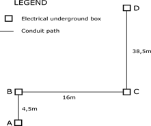
The distribution of the trajectory of the underground electrical conductor system is a trace divided into two sections. In figure 1, we can see a representation of the trace, the electrical records and the distance of each section. The total trace of the conduit is approximately 60 meters in total length.
 (Source: Own elaboration)
Fig. 1 Representation without scale of the electrical registers and the sections of underground pipes of the branch to supply the energy to the grain mills
The grain mills are provided with three-phase asynchronous electric motors and the following sheet metal data:
Manufacturer: SIEMENS
Power: 4HP
Engine reference: 1LE0141-0EA86-4AA4
Rated speed: 3505rpm
Efficiency: 87,5%
Power factor: 0,87
Rated voltage: 220V
Rated current: 10,3A
Torque: 8,2Nm
Starting current: eight times the rated current.
There are three grain mills of the same type for the grain processing premises. Since there are no representative single-phase loads and since the lighting is natural, supported by very little luminaire power, it is assumed that the load is balanced in the three phases. Taking this into account, a 10AWG THHN is selected as the electrical conductor for each phase. According to the electrical conductor manufacturer's specifications, this product saves more space in the conduits compared to other manufacturers, with easy installation and a design that helps to minimize conductive electrical losses. The electrical cable has specifications to work in voltages up to 600V, with a working temperature of 90°C and a maximum current of 40A. The cable sheath is 90°C polyvinyl chloride (PVC) with a Nylon outer jacket. These conductors comply with the NTE INEN 2345, UL83 and ASTM B3 regulations.
The electrical supply provided by the National Electric Company, it’s made up of a bank of transformers in open delta configuration, at 240V root mean square (rms) nominal voltage between lines, where the lighting transformer is 37,5kVA , and the power transformer is 25 kVA . We then have a 4-wire three-phase network, where Uan = Ubn = 120V effective and the voltage Ucn = 208V rms.
Electrical conductors have a electrical resistance per conductor to direct current expressed by equation (1).
 (1)
(1)
Where:
ρ |
is the specific resistance of the material expressed in Ω∙ mm2/m. |
l |
is its length in meters. |
r |
is the radius in mm. |
π |
is pi. |
Rcc |
is electrical resistance per conductor in ohm. |
We can then determine the total losses of a balanced three-phase electrical network for an rms current (Is) per conductor, by the following equation (2).
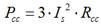 (2)
(2)
Where
Is |
is the current per conductor in amperes |
Pcc |
is the total lossesof a balanced three-phase electrical network in watt |
The skin effect in the conductors will not be considered due to the low frequency of 60Hz that is being worked on. In these cases, for a frequency of 60Hz, the depth of the skin effect is 8,47mm, having conductors with a radius of approximately 1,294mm, the skin effect cannot be appreciably expressed by varying the electrical resistance for these conditions, since the depth of the skin effect is much greater than the radius of the conductor.The harmonics are not considered in the network, which could introduce variations in electrical resistance for each harmonic and other negative effects.
This first analysis does not contemplate the effect of harmonics since simulating the results when there are harmonics is more complex, and the behavior without them must first be seen for simplicity. Finite element analysis is a large consumer of computing resources, so it is necessary to start with simple and fast models before moving on to more complex situations. We are also starting from the fact that the harmonics are at a low or negligible level for the electrical network that is under study. The power delivered to the load can be calculated, taking into account the voltage drop in the three-phase conductors, for this the Ohm’s Law is applied, neglecting the possible contribution of the reactance of the conductors, for being of low voltage and small power.The simulations for this case showed that the proximity between the conductors contributes little to the total electrical losses for the maximum current that circulates, since the length of the conductors is too small for the effect to be representative.
The analyzes require taking into account the behavior of Eddy currents, estimated in a domain of at least two dimensions. To do this, we will use the alternating current that circulates through the conductors as the source of the Eddy currents. The electrical quantities estimated by the computer program for eddy currents are the magnetic field (H) and the magnetic flux density (B). Derived quantities such as forces, energy, losses, and impedances can be determined from the magnetic field of the solution. Eddy currents are generated when there is a fluctuating magnetic field in the presence of a conductor or there is relative motion between the conductor and the magnetic field. The Eddy current field modeler and simulator calculates by solving for A and φ in equation (3), information extracted from the help of the computer program.
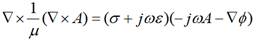 (3)
(3)
Where:
A |
is the magnetic potential vector. |
φ |
is the scalar electric potential. |
µ |
is the absolute magnetic permeability. |
ω |
is the angular frequency at which all magnitudes oscillate. |
σ |
is the electrical conductivity. |
ε |
is the absolute permittivity. |
It is assumed that all waveforms involved in the problem have the same representation as the sinusoidal current. The angular frequency is the same for all magnitudes.
Geometries and materials
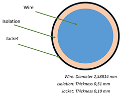
The manufacturer's electrical cables are made of a single filament, covered with a PVC insulating material and as a top layer, a Nylon jacket. Extracting from the manufacturer's data sheet, the geometric characteristics of the conductor were determined, which are shown in figure 2.
 (Source: Own elaboration)
Fig. 2 Shape and geometric dimensions of the 10 AWG THHN electrical conductor
The copper used for the active part of the solid electrical conductor is soft-tempered copper, for which we set a relative permittivity of 1 and volume conductivity of 58∙106siemens/m as electrical parameters. These are the minimum essential parameters that are necessary to model the electrical conductor with finite elements. In the case of Nylon, as electrical parameters we have a relative permittivity of 1 and a volume conductivity of 1000 siemens/m. We estimate PVC with the following properties of relative permittivity of 2,7 and zero volume conductivity.
The aluminum pipe is 50mm inside diameter, with a 3,0mm wall thickness. These data are obtained from the UNE 38058 standard. We also have that aluminum has the following electrical parameters: relative permittivity of 1,000021 and volume conductivity of 38·106siemens/m.
Electrical losses
Electrical losses is one of the most important aspects in the supply of energy in electrical power systems. The efficiency of the system depends on being losses, which indirectly affects the national economy, the import of fossil fuels, the plans of measures to increase efficiency, among other aspects of management of electrical networks. We then have to classify losses into two groups: technical and non-technical losses. Non-technical electrical losses can be named in other works as black or commercial losses. The energy generated is not fully invoiced, so this energy generated and not invoiced corresponds to non-technical electrical losses according to the literature consulted. These electrical losses can be due to the theft of energy from the supply company or due to errors in the accounting of the delivered energy.This type of electrical losses is not analyzed in this work.
Technical electrical losses are the component of electrical losses made up of the energy that is lost during the operation of equipment, networks and other components that are part of the electrical power system. The losses as a result of the natural heating of the conductors are part of these technical electrical losses. It is possible to determine or measure this type of electrical losses in electrical power systems. As these losses are linked to the very principle of operation of electrical systems, they cannot be completely eliminated, so work is being done to reduce them by improving the electrical network. The causes that originate this type of technical losses are the Joule effect, hysteresis losses in magnetic materials and Eddy currents (parasitic current). Hysteresis losses are found in the cores of transformers, which are the result of the movement of magnetic domains in the steel sheets as a result of an alternating current. In the electrical conductors present in electric power lines, these losses are not taken into account, only then analyzing the losses due to the Joule effect and those of the Eddy currents. We must know that Eddy currents are parasitic currents that are induced in the conductive parts as a result of the magnetic fields of the current that circulates through the electrical conductor.
The author in [21], mentions the use of the NEC-10 standard in the installation of electrical conductors, which take into account general aspects without considering the aspect of electrical losses in the networks. In general, the concerns are the capacity of the conductor and the voltage drop in them. In the same way, electric companies focus on the mitigation of electric losses in transmission and distribution, where the losses in the consumers as a result of being measured together with the energy consumed, in the energy meters of the clients, is not generally relevant. Electrical losses in consumers is not regulated by electrical companies. We have that the concerns of technical losses are relevant for electric companies until reaching the energy measurement points for customer billing purposes. It can be seen in the recommendations of the Latin American manual for the control of electrical losses [22], it is advisable to have total losses of no more than 3,4% in the transmission and subtransmission stage, and in the case of the distribution stage, no more than 3,2%. However, there are no details regarding the allowable electrical losses in the conductors after the energy meter.
The situation in Latin America and the Caribbean is quite different from the OLADE recommendations in [22]. In the reality of power transmission and distribution systems, the losses are several multiples higher than the recommendations. According to statistics reported in [21, 23, 24], as an average in the region, each year 17% of the energy generated is lost, taking into account that 20 of the 26 countries have energy losses greater than 10%, and 12 of 26 countries, these losses exceed 17% of the generated energy. In figure 3, we can see the behavior of electrical losses in the region [23], where the losses include technical and non-technical component. The axis of the abscissa is in years, while we have the ordinates in electricity supply in percent of total losses.
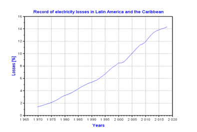 (Source: extract from [23])
Fig. 3 Behavior of electrical losses by years in the Latin American and Caribbean region.
Although the recommendations of not exceeding the losses of electrical energy are based on the economic aspect and on a good operation of the electrical networks, in reality, for political, financing and historical reasons, there is no reduction of losses to values below the recommendations of 6,6% according to [22]. The situation of the technical electrical losses in the networks belonging to the clients, has widely dispersed values with respect to the average and with much less information compiled in the bibliography. Also as mentioned above, the regulations are focused on the capacities of the conductors and on maintaining a controlled voltage drop, which is not enough to have an efficient electrical network.
In addition to what was mentioned above, in Cuba, the domestic sector is 36,3% of the total consumption of electrical energy, surpassing all other sectors, including industry, which is 25,4%, as mentioned in [25]. Which means that being the most liberal regulation in the domestic sector, it would be interesting to be able to study and economically analyze the reduction of electrical losses due to the Joule effect and parasitic currents. The case of Cuba began with electrical losses of 14,3% of total energy generation, so the national energy revolution seeks as a premise the reduction of losses to 10%, indicating in [25], where the 10% is an acceptable international margin.
The previous analysis does not take into account electrical losses in the consumer network, downstream of the electrical energy meters, which, although billed together with the actual consumption of electrical equipment, affects the performance of the electrical network in its whole. Energy saving plans in Cuba seek to reduce demand during peak hours, but an increase in efficiency in consumer networks also supports demand reduction and a more rational use of energy, with benefits for customers of lower billing.
In the work carried out in [26], which studies the methods for estimating electrical losses in secondary distribution networks, considered the last section of the service provided by electrical companies, they are taken into account until the connection, that is, until the point of measurement of electric energy for billing. The work presented is considering the losses below the energy measurement point in the connection, and therefore, not normally considered within the estimates of losses by electric companies.
Analysis cases
Each case under analysis is using the estimated full load current of the grain mills, which we will use as a reference for all simulations. We will then have the analysis of different ways of accommodating the electrical conductors within the aluminum pipe and its analysis in terms of the electrical losses produced by the circulation of estimated current at full load of the electrical circuit. As a counterpart, these results are compared with the equivalent PVC pipe, to understand how much energy is wasted when using aluminum instead of PVC.
So the comparison will be between:
Losses between the aluminum material vs. PVC.
Effect of the approach of the group of conductors towards the pipe wall.
Changes in the distribution of conductors inside the pipe.
In order to compare the losses between the aluminum material and the PVC in buried pipes, a two-dimensional analysis will be carried out by means of finite elements of the Eddy current at an alternating current of 60Hz of linear frequency.
The losses depend on the geometries, the distribution of the conductors within the pipeline, as well as the distance from the tube wall. This analysis is carried out to estimate the effect on electrical losses as a function of the distance from the tube wall. A distribution of the conductors is fixed for the analysis, because different configurations in the distribution of the conductors change the values of losses depending on the distance. We will have as a last analysis, the fact that the conductors rest in the lower part of the pipe, due to the effect of gravity, so we will see different configurations of the distribution of the conductors. This makes it possible to select from these configurations the one that produces the least losses.
Results
We obtain the comparison of the effects of the aluminum material as opposed to the PVC of the behavior of the magnetic field and of the total electrical losses due to the effect of the resistance of the conductor and the eddy currents. In figure 3 a) and b), we can see the behavior of the field for the case of aluminum. In figure 4 a) and b), we can see how the field is affected when using PVC for the pipe material. The distribution of the magnetic field reflects how the material aluminum influences. There is a disturbance in the field, the result of a shielding of the field, with which it reaches lower field values outside the pipe.It is possible to observe how the magnetic field changes when it meets the wall of the pipe. Resulting in an increase in losses due to parasitic or eddy currents.
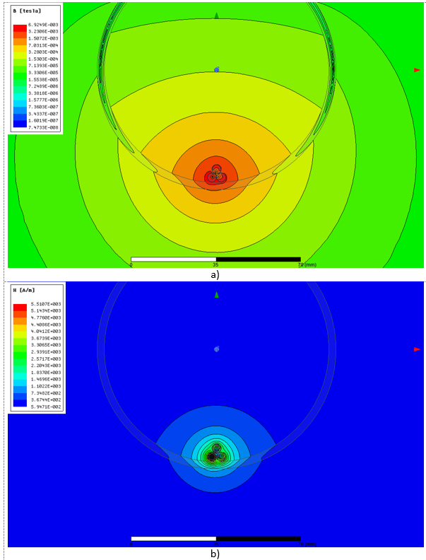 (Source: Own elaboration)
Fig. 4 Case of the distribution of the magnetic field in the frontal plane of the electrical conductors with the aluminum pipe: a) Distribution of B. b) Distribution of H.
The first thing that can be appreciated is that the distribution of the magnetic field in its two components (B and H) is not altered by the PVC material, as it is affected by the aluminum of the tube walls. The electrical losses for the case of using PVC as the pipe wall are 368,78W. The use of aluminum produces a difference of 12,58W, for losses of 381,36W. Aluminum, at the cost of an increase in electrical losses, creates a decrease in the field outside the walls of the pipe, creating a small deformation of the natural concentric field.
For the displacement of the group of conductors in the same configuration as that shown in figures 4 and 5, a parametric analysis of the losses is carried out as a function of the proximity to the wall of the pipe. The results are shown in figure 6, through the use of Scilab software.
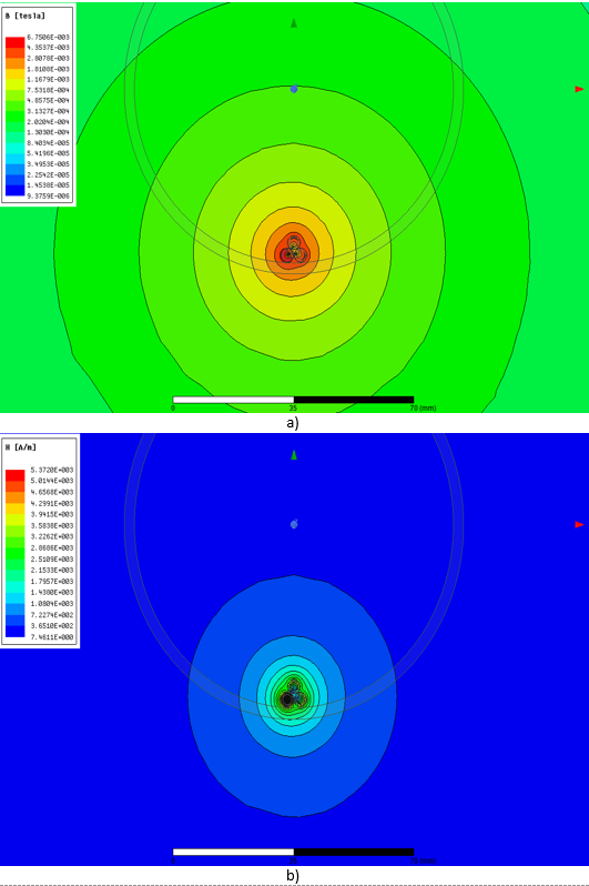 (Source: Own elaboration)
Fig. 5 Case of the distribution of the magnetic field in the frontal plane of electrical conductors with PVC pipe: a) Distribution of B. b) Distribution of H.
 (Source: Own elaboration)
Fig. 6 Graph of the behavior of electrical losses when bringing the conductors closer to the wall of the aluminum pipe
As it is verified in the results in the graph of figure 6, we have an increase in the electrical losses when the group of conductors is brought closer to the wall of the aluminum pipe, in a progression with each time greater increases in the losses per unit of distance. The last case is the change of the configuration of the conductors of the three phases inside the aluminum pipe. To do this we will change the distribution of the conductors to an arrangement of one phase next to the other, changing the order of the phases from left to right. See figure 7.
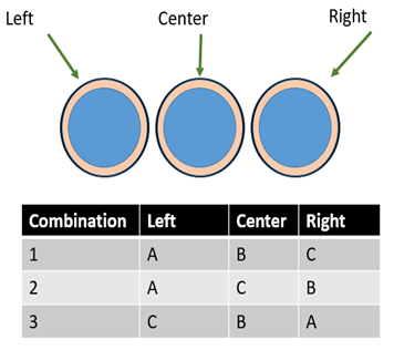 (Source: Own elaboration)
Fig. 7 Conductor configurations for the analysis of losses at the bottom of the aluminum duct
For the analysis carried out with the three balanced conductors, there are no differences in electrical losses. Any of the combinations of figure 7, can be used, because there are no appreciable changes. The losses in these three cases are approximately 381,79W. These configurations have a slight increase in losses over the triangular configuration of the conductors inside the duct. In figure 8, we can see how the component of the magnetic field B is distributed inside the duct.
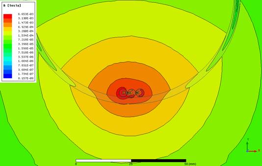 (Source: Own elaboration)
Fig. 8 Distribution of the B component of the magnetic field inside the aluminum duct for the ABC configuration
The magnetic field extends to the sides, instead of being more concentrated as in figure 3 a). It should be noted that it helps that in all cases the losses in the pipeline as a result of Eddy Currents are lower, it is the internal dimensions of the duct that are considerably larger than necessary, and it is in principle selected by the availability on the farm of this type of pipe.
Discussion
The use of local materials for construction has many advantages, such as being sustainable over time. This choice of local materials positively influences the environment and nature. The use of materials that were to be discarded is key to sustainability, as there is economic potential for new companies to manage and help recycle. This is why the use of aluminum pipes instead of PVC ones contributes with the aforementioned advantages. From an energy point of view, the manufacture of PVC pipe requires large amounts of energy in the extrusion machines.
Then we select the case of lower electrical losses with the use of the aluminum duct: triangle configuration of the conductors. In the following table 1, we summarize the main results of the proposal.
Table 1 Results of the selected configuration with lower energy losses
| Parameter | Quantity | Unit of measurement |
|---|---|---|
| Electrical resistance of a conductor | 0,1961604 | ohm |
| Effective current per phase | 25,0 | amperes |
| Three-phase electrical losses in conductors | 368,78 | watts |
| Losses in the walls of the duct | 12,58 | Watts |
| Total electrical losses | 381,36 | Watts |
| Power on load | 8,288 | kilo watts |
| Active power delivered by the bank | 8,669 | kilo watts |
| Efficiency | 4,6 | per cent |
Electrical losses in a supply network cannot exceed the average of 2% in high voltage, 4% in medium voltage and 8% in low voltage [27]. The losses of the farm connection were calculated, and we have technical losses of 0,99% at full load, with estimated losses in the transformer of 2%, we can say that we have maximum losses of 7,59% at the all circuits. Because the distribution transformers are very efficient (<2%), and the rest of the section of conductors is very short compared to the 60 meter branch, we can ensure that low voltage losses of a maximum of 8% are met. Losses are considered excessive when they exceed 10%. For the cases of the use of aluminum or PVC pipe, a 5-year economic study of the rate of benefit against cost (B/C) was carried out. The results showed that the use of PVC pipe has a B/C=1, 2.
The use of aluminum has a lower initial investment, with slightly higher electrical losses than the other case, with a B/C=1,44. This shows that it is more economical to use aluminum pipe for this particular situation under study.The economic weight falls on a lower initial investment, by not having to buy pipes to make the underground channeling. Underground power grids are used to transport electricity over long distances, safer, more reliable, and more aesthetically pleasing than overhead lines. Aluminum also has the advantage that it dissipates heat much more easily than PVC, allowing the heat generated by conductors to be released to the environment much more easily.
Conclusions
The proposal to use aluminum irrigation pipes to implement an underground duct for a group of grain mills was analyzed using the two-dimensional finite element method and the rate of benefit against costs in a period of 5 years.The economic indicator confirms that the use of aluminum pipes would provide better financial health. Various possibilities of conductor distribution were analyzed, as well as the effect of the distance of the electrical conductors from the duct wall.Through the results of the simulation by finite elements, it was possible to determine, among the different cases analyzed, which was the appropriate distribution of conductors with the lowest electrical losses.
The results showed that the total losses in low voltage for the case of the use of aluminum as underground pipe is 7,59%.Therefore, the consulted literature reports that low voltage electrical loss values of less than 8% are for a good electrical network.This indicates that we are within the acceptable range of electrical losses. The use of finite elements facilitated the analysis of the different cases, as well as being able to carry out the sweep of the losses with great flexibility depending on the distance of the conductors from the center of the pipe. It is a tool that facilitates understanding the geometric effects that affect the behavior of electromagnetic fields.

