


 Serviços customizados
 Espanhol (pdf)
 Artigo em XML
 Referências do artigo
 Enviar este artigo por email
 Citado por SciELO
  Similares em
SciELO
Similares em
SciELO 
 Permalink
Introduction
The problem of reactive power control is crucial in electrical power systems, since reactive power is necessary to maintain the voltage at adequate levels in electrical power systems. When there is a lack of reagent control, problems such as voltage drops, overloads on transmission lines, and loss of system stability can occur. Reactive control involves the generation, transmission and absorption of reactive power to ensure safe and efficient operation of the electrical system. Various techniques, such as reactive compensation, automatic voltage control and the use of flexible alternating current transmission system (FACTS) devices, are used to address this problem in electrical power systems. Reactive power (generated and consumed by generation, loads and transportation) is present throughout the electrical system [1, 2].
Reactive compensation in power systems refers to the installation of equipment to produce reactive power locally and mitigate reactive consumption by the network. This compensation can be achieved through different elements, such as thyristor-switched capacitors (TSC) and thyristor-switched coils (TSR) or controlled (TCR), which are part of the Static Reactive Power Compensators (SVC). SVCs have their main application in voltage control, to maintain voltage profiles within the allowed bands and provide a quick reserve of reactive power in case of contingencies and transient phenomena. Reactive compensation is important to improve the quality of the electrical system, correct the power factor and reduce losses in the network [3, 4].
The advantages of using a static reactive power compensator include, according to references [5, 6]:
Increase in the transportation capacity and adequate sizing of the installation, due to the decrease in the effective value of the intensity consumed by the load set plus compensation equipment.
Reduction of losses in the electrical system.
Maintenance of voltage, due to the relationship between reactive power and voltage.
Savings in billing, since legislation can apply a surcharge if reagent consumption exceeds certain limits.
On the other hand, the disadvantages of static reactive power compensators are according to references [7, 8]:
Its reactive power generated depends on the voltage, which can limit its effectiveness in certain conditions.
They are sensitive to harmonics and their inclusion in the network can cause resonances with the inductive elements existing in it.
Their aging affects the reactive power they are capable of generating.
They influence the stability of the electrical machines present in the network.
Its installation involves considerable assembly and maintenance costs.
To learn how to use an SVC, it is necessary to acquire theoretical and practical knowledge about its operation and application in power systems. Some steps to learn how to use an SVC include [9]:
Study the theory behind reactive compensation and the operation of SVCs in regulating voltage and reactive power.
Become familiar with the components and configuration of an SVC, including thyristor-switched capacitors (TSC) and thyristor-controlled coils (TCR).
Learn about the applications and benefits of SVCs in improving electrical power quality, system stability and loss reduction.
Gain hands-on experience through simulations and case studies involving the installation and operation of SVCs in power systems.
It is then necessary to have a robust foundation of reactive compensation theory, the relevant electronic models for SVCs, as well as sufficient experience through simulations and their respective case studies. Due to the significant load of essential competencies to master this discipline, a centralization towards the relevant aspects is required, eliminating issues of mastery of specific software and other areas of knowledge, to streamline and gain clarity in the teaching-learning process based on competencies [10]. In university teaching aimed at professionals in the electrical branch, the control of reactive power, as well as the magnitude of the power factor, requires a complex approach to the solution, with different solutions and an economic and legislative dimension involved in any proposal technique. To understand the effect of changes in reactive power, students need to have mastery of electrical circuits, electrical power systems, technologies and means for compensation, as well as knowledge of electronics, mathematics and digital signal processing. Traditionally, the teaching methods on the topic of reactive power compensation are based on a series of typical cases, supported by the corresponding demonstration methodology based on alternating current electrical circuits.
Here the use of phasor diagrams, waveforms and mathematical definitions is needed. The problem is that the information and demonstrations presented in teaching activities are typical images. One of the solutions for a more dynamic, demonstrative class that allows active student participation is the use of simulation software. It is with the use of simulation software that students achieve a more advanced step in understanding reactive power, they can actively make hypotheses and verify the results by obtaining the corresponding magnitudes and graphs. Without a doubt, it allows the student not to act as a listener, but to play an active role in their education, by participating and proposing changes in the model, checking during the teaching activities and even independently, how to solve power control problems reactive. The main limitation is that generally in order to understand what happens in the simulation, there must be a mastery of the tool used to model and finally simulate the behavior of electrical power systems. This includes, as mentioned above, multiple areas of knowledge such as mathematics, electrical power circuits, digital signal processing and many other aspects. Which causes the attention of the main phenomenon under study to be diluted in a scattered attention to many important details of the solution, or even to fundamentally issues of use of the specific software.
It has been observed that then with other simulation software, which constantly change in the computerized world, the student requires training to be able to reacquire the skills to carry out a deep and systematic study of a proposed solution to the compensation of reactive power. To achieve this objective in university teaching, it is necessary to use professional free software, which favors the performance of theoretical - practical - experimental exercises for the training and development of professional skills. This enables better preparation of students with the purpose of achieving professionals capable of responding to the various problems and situations related to the profession [11]. The incorporation and integration of ICT in the field of education has evolved over recent years, as its use has gone from being a possibility to establishing itself as a necessary teaching medium to improve the quality of the teaching process - learning for both teachers and students.
On the other hand, and no less important, starting in 2018, the E study plan is implemented in the Electrical Engineering career of the University Technological of Havana “José Antonio Echeverria”, CUJAE, as a result of the curricular improvement process that is carried out in Cuban Higher Education. This improvement conceives among its conceptual bases the need to achieve a higher level of essentiality of the contents in the disciplines to guarantee comprehensive training of students and application of knowledge in problem solving. One of the premises for developing these plans and carrying out curricular improvement is the importance of achieving qualitative transformations in the training process as a consequence of a wide and widespread use of Information and Communication Technologies. Furthermore, as part of this improvement, the technical management of the Unión Eléctrica, requested that a series of topics be included in the course that will be part of the contents to be taught, such as the study of flexible alternating current transmission systems.
For these reasons, it is necessary for the teacher to apply teaching-learning methods supported by ICT to achieve developmental learning in accordance with the social demands related to vocational training. With the integration of technologies in teaching-learning methods, education tends to be deployed as an open and continuous system that demands the innovation of modern pedagogical guidelines to benefit autonomous and independent study, joint work, the development of techniques interactive communication and knowledge appropriation, influenced by the dialogic action between teachers and students, as well as by the use of new information and communications technologies [12, 13, 14, 15].
Competency-centered teaching is characterized by giving a leading role to the student in the teaching-learning process, while the teacher acts as a guide and facilitator. In this approach, the emphasis is on the development of practical skills and knowledge applicable in real contexts. Learning assessment focuses on measuring the competencies acquired by the student, often through direct observation of the application of knowledge and skills in concrete situations, rather than relying solely on theoretical exams. The use of software technologies and tools, such as Python and the Matplotlib library, can be beneficial in competency-focused teaching, as these tools can help simplify the analysis of electrical circuits and create an interactive teaching-learning environment.
To achieve learning focused on the relevant concepts, without diluting the students' attention to the details of the application used as a teaching tool, it was decided to use the circuit description and modeling language “spice”. This language is widely used by electronic component manufacturers and has a long history of success, so much so that many manufacturers provide models of their components for use in a wide variety of software. Then the student will learn “spice” models with a broad base of applications that use them, generally provided by recognized electronic component manufacturers, as well as well-established in the technological field of electronics and simulation programs.
In daily work with electrical circuits, complex manual calculations and drawings are often performed. These manual circuit analysis methods are laborious, time-consuming, and error-prone. In this context, the Python programming language is presented as a solution that can significantly improve circuit analysis. Python is a general-purpose, high-level interpreted programming language that is widely used in computer science and scientific engineering. Using the Matplotlib library to draw sinusoidal alternating current graphs, together with the Python programming language, simplifies the analysis and creates a friendlier working environment. For all the above, the objective of this research article is to propose an application that allows the study of reactive power compensation in electrical power systems that helps improve the teaching-learning process of the subject of Power Electronics.
The fundamental scientific contributions made in this work are:
Achieve the independence of a specific software package for the teaching-learning process of reactive power compensation, with models developed in the standard electrical circuit description language “spice”.
Enhance generalized programming logic skills for those students who are advanced or who want to delve deeper into simulation media.
Implementation of models through circuit description through “spice” of typical cases of the behavior of the reactant, the thyristor-controlled reactor and the thyristor-switched capacitor.
Materials and methods
In order to develop the objective of this research, it was necessary to verify the existing theoretical studies and the search for the scientific knowledge accumulated around the search for methodological applications on the integration of ICT in the teaching-learning process, as well as such as the use of free professional software in university teaching. The study was based on a qualitative descriptive methodology, in which the methods of the analytical - synthetic and inductive - deductive theoretical level were used to examine the existing theoretical positions regarding the need and importance of integrating ICT in the teaching process. -learning and its possible applications in the subject of Power Electronics; Document analysis methods and the systematization of bibliographic sources that serve as references for this work were also used, expressed in the investigations of the references [16, 17, 18, 19, 20].
The software used for the proposal through simulation is the free software Python, which allows graphical representation, mathematical treatment and calculation of functions, very useful for the development of applications in electrical engineering. As an empirical level method, the structured interview was applied to know the students' opinions about the usefulness of the tool for the study of reactive power compensation in electrical power systems that helps improve the teaching-learning process. of the Power Electronics subject. The population was made up of 70 students of 4th year of the Electrical Engineering degree at the University Tecnological of Havana “José Antonio Echeverría”, CUJAE, in the period 2023, which represent 100% of the enrollment. As a statistical method, the calculation of absolute and relative frequencies was used for the processing and analysis of the information obtained in the interviews carried out.
Discussion and results
Reactive power compensation models
In order for the student to appropriate the knowledge about reactive power compensation, it is necessary to carry out the analysis of several typified cases. Therefore, we must start with the simplest case, up to the use of power electronics techniques to compensate for the use of reactive power in alternating current lines or loads.
The typified cases are the following in order of development in the educational process by competencies:
Behavior of the active and reactive component of an alternating current load and power factor compensation by means of a fixed capacitor bank.
Behavior of the active and reactive component in the presence of a concentrated load and its feeder, with analysis of the effect of a fixed capacitor bank.
Principle of operation of a thyristor-controlled reactor.
Principle of operation of a bank of capacitors switched by thyristors.
The cases mentioned above are the basis for the operation of much more complex equipment, which is static reactive power compensators. Therefore, it is convenient to break it down into independent models for better understanding by students. In figure 1, you can see the four circuit models for reactive power compensation.
 Own elaboration
Fig. 1 Circuit models for the study and teaching of reactive power compensation with SVC a) Simplified model for analysis of the effect of the capacitor in the control of reactive power b) Model with effect of the line impedance on the reactant c) Reactor model controlled with thyristors d) Switched capacitor bank with thyristors.
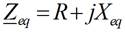
Although these circuit models are relatively simple, the compensation of reactive power and its control is not. It requires precise control of the bidirectional switches, as well as step or phase control strategies for the switching of the power thyristors. The first thing to take into account is how the final equivalent reactant affects when connecting a capacitor in series with the load, case a) in figure 1. This model is based on a concentrated load with a resistive and inductive component, where the inductive component. For this case, the resulting impedance is equal to that shown in equation (1):
 (1)
(1)
Where the reactance Xeq is the product of the angular frequency times the equivalent inductance of the concentrated load and R represents the resistive part. Therefore, knowing the voltage with which the load is supplied, the current that circulates through it can be determined through equation (2).
 (2)
(2)
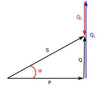
Knowing the current then, it is possible to calculate the apparent power (S), the active power consumed by the load (P) and the reactive power (Q). The reactive power can be inductive (QL) or capacitive (QC) depending on whether it is treated by an inductor or capacitor respectively. The angle between active and apparent power, denoted by (φ), can be determined by equation (3).
 (3)
(3)
Where cos(φ) is also known as power factor. The relationship between the powers and the impedance angle is related through the power triangle shown in figure 2.
 Own elaboration
Fig. 2 Relationship between active, reactive and apparent powers, with the power factor.
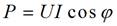
The active power is calculated by means of equation (4), which relates the effective current and voltage to the power factor.
 (4)
(4)
To calculate the reactive power, equation (5) is shown.
 (5)
(5)
Now there are two ways to determine the apparent power S, by means of the Pythagorean Theorem, or simply by applying equation (6).
 (6)
(6)
From figure 2, it can be seen that the greater the reactive power Q, for a constant active power, the lower the power factor and, therefore, the greater the circulation of the current, increasing the electrical losses in the components of the electrical system. of power, to bring the power P to the load. It is for this reason that we seek to raise the power factor to values close to unity. Although the improvement of the power factor can be achieved by connecting a capacitor or bank of capacitors in parallel with the load, the variability of the working conditions in electrical power systems makes a fixed equivalent capacitor impractical. since if there is more capacitive reactive than the inductive reactive of the load, there may be overcompensation, which can cause the voltage in the system to rise above the maximum allowable values, or worse, irreversible damage to the loads or the system may occur own electrical system.
That is why in cases that require a better dynamic response, with short response delay times, the use of bidirectional switches is resorted to (generally through the use of power thyristors), where static VAR compensators are generally the solution. This type of compensator has a series of combinations, consisting of banks of fixed capacitors, thyristor-controlled reactors (TCR) and thyristor switched capacitors (TSC). To control capacitors with bidirectional switches, it is common to find two to four units, which are connected at the instant of time that produce the lowest starting current, and are used in a stepwise manner to obtain the discrete equivalent capacitive reactance. In the case of reactors, these are switched by varying the firing angle of the switches, and there is an inductive reactive power dependent on the connection angle.
Its main disadvantage is that the current is not sinusoidal, creating current harmonics. To avoid the circulation of harmonics in the network, reactors are generally connected in delta so that the 3n component (n is the harmonic index) circulates within the delta and not to the electrical network. The fifth and seventh harmonics are reduced by tuned filters. The models are implemented using the “spice” language that allows describing each element of the circuit through references to the nodes and the elements' parameters. For example, an inductor will be modeled as “L1 N1 N2 4e.3”, where the first term defines the inductor element (L) by the first letter, with the following letters or numbers as the name. The second and third element defines the positive and negative node where the inductor is connected. The last element being the value of the inductance. Similarly, capacitors, resistors, sources and other elements are declared in “spice”.
To develop the proposed graphical interface application, the objectives of the Electronics subjects were analyzed and different methodological activities were carried out in the discipline with the aim of identifying which are the most important aspects that must be improved with a view to implementing the learning approach based on issues. From these analyses, the most up-to-date configurations were determined when analyzing the static reactive compensators. It is important to highlight that through simulation the student forms and develops skills for solving professional problems through trial - error, learns systematically, applies his knowledge in practical activities, in addition to receiving feedback to improve his learning and thus significantly reduce errors.
In that sense, the application was made up of a first version with four configurations implemented in Python and using Ngspice to simulate the circuit models shown previously, from which four variants of virtual laboratory practices were carried out to improve the process. teaching - learning of Power Electronics subjects. It is important to note that the description of the models can be accessed in “spice”, since these are printed in a console that runs in the background and in text format. The work sequence is simple: the data is entered; the program is executed and waveforms and relevant magnitudes are obtained in numerical format. By analyzing the results together with the students, conclusions are reached and the knowledge imparted during the theoretical explanations is solidified, avoiding diluting the explanation with technical issues of the program itself or programming peculiarities.
All developed programs have a similar interface separated into five sections:
Circuit that describes the model.
Brief description of the model and what to expect.
Model data entry section and run the solution button.
Numerical simulation results.
Complementary materials such as technical documentation or program help
Each program opens auxiliary windows for graphs and in some cases, animated graphs to help better understand what is happening in the model.
VARIANT T1
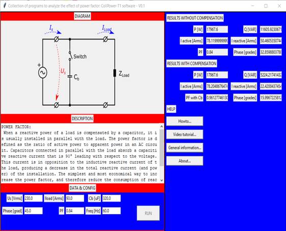
The T1 variant is responsible for explaining how reactive power compensation works and the effects of the angle between voltage and current on the load. This is the simplest case study and is where students must synthesize the fundamentals of power factor compensation or improvement. In figure 3, you can see the program interface. The necessary input data are the rms voltage and its angle at the source, the rms current, the power factor, the capacitance and the operating frequency of the network. Power factor can be obtained directly from energy meters without additional instruments in many cases. This creates the opportunity for students to explore real cases without complications or resources beyond those they may find in major loads.
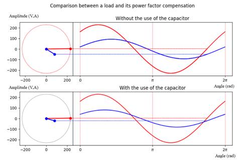
This program incorporates visual means of comparison between phasor diagrams and waveforms over time. This adds appeal and motivates students with details that are generally static images and require detailed explanation to understand the logic behind them. Figure 4, shows a screenshot of the animation of the results of the program execution. The image is divided into two rows, where the top one is the phasor state of the charge without a capacitor. The bottom row includes the capacitor in parallel with the load. It is in both phasor diagrams integrated with the waveforms in time, that you can not only appreciate the difference in the angle between voltage and current, it can also be observed with dashed and colored lines as time passes in the form of wave, the phasor diagram rotates appropriately. The red color is for voltage magnitudes and blue for current.
The main advantage of using phasor diagrams is that the difference in the angle between voltage and current is better appreciated, which denotes how the power factor and reactive power behave in the electrical power system. Students can run cases directly, and rely on the results and effects of the capacitor, without risking accidentally modifying the model. It can be verified in this case that the active power remains constant, and is the change in the reactive power, due to the algebraic difference between the inductive reactive and the built-in capacitive power that improves the power factor angle. Cases of overcompensation can be analyzed, including using the tool as a means of verifying traditional table work results.
 Own elaboration
Fig. 3 Graphic interface of the T1 program for the analysis of reactive power compensation through the simplest circuit model.
 Own elaboration
Fig. 4 Capture of the animated graphic results of the T1 program where the state of charge can be compared with or without the reactive power compensation capacitor.
VARIANT T2
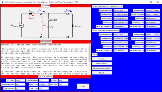
The T2 variant is a step forward in the complexity of the model under analysis. Although the T1 variant defines the fundamental issues, it does not take into account how the load's power line or the internal impedance of the source, which can be a generator or the power grid itself, affects the behavior of the power. reactive. In fact, line impedance has important effects on harmonics and introduces relevant changes in reactive power compensation studies, because current harmonics, when circulating through the line impedance, introduce distortion in the voltage waveform, which in turn can affect the current, creating a dependent circular effect. In figure 5, you can see the graphical interface of this variant. If you want the interface to be as simple as possible and easy for the student to work with, familiarization in the case of the T1 variant will be useful in future analyzes with this group of computer tools.
 Own edition
Fig. 5 Capture of the animated graphic results of the T2 program, to analyze the compensation of reactive power with a built-in line impedance.
This T2 variant also features a phasor diagram and animated waveforms like the T1 case. There are no appreciable changes between said animated response and another, between variant T1 and T2. The waveform output interface is identical.
VARIANT T3
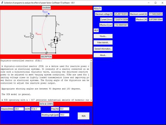
It is in this variant T3, shown in figure 6, that we begin to analyze the relevant cases for the specialty of power electronics, since we have the implemented model of the thyristor-controlled reactor. This simplified model of reactor reactant control now requires specifying the reactor connection angle in each half cycle of the source voltage waveform.
It is then from this model that several cases of the use of reactors controlled by bidirectional switches and the effects of:
Behavior of the connection current.
Steady state current.
Distortion of the current wave by increasing the firing angle of the thyristors.
Determination of maximum current
Calculation of the fixed equivalent effective inductance and reactance with respect to the inductor and the selected firing angle.
It is important that students experience multiple real situations and analyze what happens when there are changes in the behavior of the system, which in many cases are not mentioned or are mentioned briefly in the specialized literature, and which must be taken into account in a larger picture in the electrical power networks. This tool allows you to propose changes to the simulation to solve the technical problem under study. You can start with an initial configuration in the poor program, and propose that the students look for the solution. This is where active and meaningful learning is enhanced in students based on the challenge of obtaining a technically feasible solution. The numerical results are shown in figure 6, itself, in the results section. Figure 7, shows one of the three graphs obtained by a simulation of the T3 program.
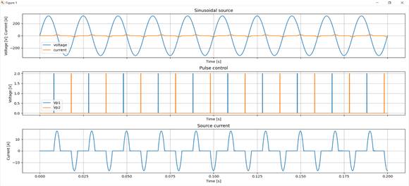
As it is observed, the current waveform is distorted into a sinusoidal waveform, having sections of zero current, with a rapid increase and decrease in the amplitude of the current at the source. That is, it can be demonstrated to students that increasing the firing angle of bidirectional switches worsens the waveform, generating harmonics. In fact, the case where there are fewer or zero harmonics is when tripping the switches at zero degrees. In this simulation, two figure windows are additionally obtained, to show the voltage and current at the source aligned in two graphs, one on top of the other. The last window creates a single graph, where are the waveforms of the source voltage, the current that circulates through the circuit for the fixed firing angle, and in dashed lines the equivalent current if a fixed reactor were used. From studying this variant, the student can come to the conclusion that this type of device can only be controlled with firing angles between 90° and 180°. Using firing angles outside this range does not create reactive current control or the device simply does not work.
VARIANT T4
The last variant developed in this first version of the proposed tool is the T4 variant, which is the model of a switched capacitor with thyristors. Unlike the case of the controlled reactor, the capacitor can only be connected to the grid or not, that is, to have control of the reactant, it is necessary to have several modules that enter into groups to obtain a stepwise regulation of the capacitive reactive power. That is, the control of the firing angle is to minimize the insertion current from the capacitor bank to the network. To disconnect, it is enough to stop delivering the control pulses to the switches, since, when the thyristor current passes through zero, it turns off naturally. Figure 8, shows the program interface in the T4 variant.

To show the effect of connecting and disconnecting the capacitor, the program simulates in period 5 the connection of the bank and a working time of seven consecutive periods before applying the disconnection. This is not user configurable unless you access the code and modify it. Action that can be carried out by an advantaged student or with an interest in programming computer applications, so the application of software in the teaching-learning process of Power Electronics subjects develops programming as a method in students.
On the other hand, the use of the inductor in series with the bidirectional switch and the capacitor is to function as a limiter of the insertion current of the system to the network. There are two possibilities according to technical proposals:
That the inductive reactance is 6% of the capacitive reactance
Choose an inductance that, together with the network frequency and capacitance, obtains a resonance frequency between 150 Hz and 250 Hz generally.
In order to analyze the effects of not appropriately choosing the relationship between inductance and capacitance, the user is allowed to enter unrestricted values of these magnitudes. It is very interesting to observe how radical changes occur in the functioning of the compensator, which helps to understand that it should not be done under any circumstances, which develops significant learning in the student through trial-error tests. In figure 9, you can see the two graphics windows generated by the program. By analyzing the graphs in figure 9, you can see the control pulse that indicates the connection to the network.
It is also possible to appreciate the moment of connecting the capacitor to the network, showing a disturbance in the current, until it stabilizes in a sinusoidal shape. By changing the connection angle of the capacitor, more radical effects can be seen for increases much higher than the nominal current of the capacitor. This is one of the most important issues, because when false trips or faults occur at the moment of connection of the capacitor, a transient condition occurs that can cause openings of switches to protect the network by mistake, when confused with a short circuit current.
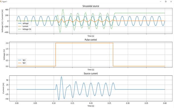 Own edition
Fig. 9 Capture of the graphic results of one of the windows of the T4 program, to analyze the TSC.
On the other hand, it is important to highlight that with the objective of knowing the practical usefulness of the proposed models and the developed application, a total of 70 4th year students of the 2023 academic year were interviewed, which represent 100% of the enrollment and who They have already taken the Power Electronics subjects. The form that served as a guide for conducting the interview was structured as follows:
Question No. 1. In your opinion, do you consider that using the models created in the Python software for the SVC analysis helped you reinforce the theoretical-practical contents, as well as the development of skills?
Question No. 2. In your opinion, did the use of the proposed application and the knowledge acquired with its application help you improve motivation for the race?
Question No. 3. In your opinion, did carrying out the activities using the proposed application help you exchange knowledge and skills with your colleagues?
The interview responses are shown in table 1.
Table 1 Interview results
| Results of Question No 1 | ||
|---|---|---|
| Frequency | % | |
| Yes | 70 | 100 |
| No | - | - |
| Total | 70 | 100 |
| Results of Question No 2 | ||
| Frequency | % | |
| Yes | 70 | 100 |
| No | - | - |
| Total | 70 | 100 |
| Results of Question No 3 | ||
| Frequency | % | |
| Yes | 70 | 100 |
| No | - | - |
| Total | 70 | 100 |
Analysis and interpretation: It is observed that 100% of the students interviewed consider that the proposed application helped them understand the theoretical content taught in the lectures and develop practical skills. From these results it can be inferred that the integration of the application greatly helped to improve the teaching-learning process of students in the Electronics subjects in the analysis of control devices for reactive power compensation. On the other hand, 100% of the student’s state that the use of the proposed application together with the knowledge acquired in the Power Electronics subjects on the study of reactive power control devices helped them increase interest and motivation. for the career, because in addition to deepening theoretical-practical knowledge, applying simulation and programming as a method helps them verify the proposed exercises and interpret the results.
Likewise, 100% of the students affirm that the formation of teams to carry out the activities with the proposed application helped them exchange information regarding the use and implementation of the models, as well as the interpretation of the results. This result shows that the formation of teams and the integration of ICT in the teaching-learning process through simulation and programming improve collaborative, meaningful learning and self-learning of students, especially when applied in related problematic situations. with the profession with an interdisciplinary approach.
Conclusions
From the integration of the proposed application, the teaching-learning process of the subjects of Power Electronics specifically the study of reactive power control devices in electrical power systems. The use of simulation and programming as a method of the teaching-learning process based on application improves the learning results of students in Power Electronics subjects, since it enables a greater link between theory and practice, in addition to develop logical thinking and autonomous, collaborative, meaningful and professional learning in students. On the other hand, the developed models are characterized by being an educational resource that manages to improve the results of the teaching-learning process and turns out to be useful for students of the Electrical Engineering career, both in face-to-face activities, as well as in distance activities. In addition, it promotes personalized learning that takes into account learning times and collaboration between the students in the group and with the teacher.
The development using the Python programming language, the use of libraries such as Matplotlib and the integration with the Ngspice simulation package has allowed the creation of a group of software aimed at explaining how the reactive can be compensated in electrical power networks. Therefore, it has been possible to develop a group of tools that provide dependence on a commercial software package, to develop generalized programming logic skills as the code is accessible to students.

