


 Servicios personalizados
 Inglés (pdf)
 Articulo en XML
 Referencias del artículo
 Enviar articulo por email
 Citado por SciELO
  Similares en
SciELO
Similares en
SciELO 
 Permalink
Introduction
The method of symmetrical components presented by Fortescue in 1918 allows the analysis of unbalanced networks in a simplified way. This theorem shows that to solve an unbalanced system of n-related phasors, n systems of balanced phasors called symmetrical components can be used [1, 2]. The application of this method to an unbalanced three-phase system is reduced to the decomposition into a sum of three phasor systems (symmetrical components); two balanced systems of positive and negative sequence in conjunction with onehomopolar system (zero-sequence) in which the phasors are of equal magnitude and phase [1, 2].
The representation of the different three-phase elements that make up the power system (generators, transformers, transmission lines, and loads) to asymmetrical faults can go expressed in three equivalent circuits in response to each of the components of the short-circuit current. Therefore,this idea allows us to understand that the sequence networks are nothing more than the connection of the sequence circuits individually, according to the connections between the electrical system elements [1, 2, 3]. Towards analyzing the sequence networks, the impedances of the elements of the system to be analyzed are required. In the case of the positive and negative sequence impedances of the linear and symmetrical elements these are considered to be the same; except in the case of rotating machines where the impedances are different for each sequence.However, zero sequence impedances vary based on the element being represented according to [1, 2, 3].
In the case of power transformers, the positive and negative sequence impedances are the same, unlike the zero-sequence impedance, which may differ slightly in value. The variations in the values of positive, negative, and zero sequence impedances in power transformers are primarily influenced by the type of transformer core. This is because the zero-sequence flux paths can differ, resulting in variations in the zero-sequence impedance [2, 3, 4]. Although these impedance differences are generally negligible, they are considered while representing the positive, negative, and zero sequence impedances in power transformers. This simplification allows for a more straight forward representation of the impedances [2, 3].
The zero sequence impedance values in transformers play an important role in calculating asymmetric short circuit currents when a ground fault occurs. However, it is also crucial to consider the connection group. The grounding of the windings is extremely important because, in short circuit calculations it may mean taking or not taking into account the zero-sequence impedance. Furthermore, their configuration allows us to characterize the behavior in the face of overvoltages or overcurrents that may occur in the power system in the event of asymmetrical faults, such as in generation plants where the objective is to reduce the magnitude of the short-circuit current gaven the generators. Given these characteristics, special cases may arise in power systems where the zero-sequence impedance of the transformers behaves differently for different faults [2, 3].
A detailed study of zero-sequence networks in power transformers is the main objective of this paper, where two special cases in which zero-sequence impedance produces important changes in asymmetrical short-circuit currents are analyzed by mathematical simulation.The paper is divided into four sections, organized as follows. After the Introduction, the Materials and Methods section presents the main features of the case studies together with a theoretical characterization of the different phenomena. The Results and Discussion section provides the reader with the main results of the mathematical simulation. The last section gives the basic Conclusions of the work.
Materials and methods
To carry out this paper, it was necessary to review the existing studies in search of theoretical knowledge about zero-sequence networks in power transformers. The theoretical-analytical-synthetic method was used, in addition to modeling, to verify the existing theory concerning the proposed case studies. The empirical method was used using mathematical simulation of the phenomena using Matlab software.
Zero sequence networks in power transformers
According to [2, 3], the sequence equivalent circuits in power transformers depend on the connections of the primary and secondary windings. Depending on the wye or delta connection, the configurations of the zero-sequence networks and the phase shift in the positive and negative sequence circuits can be determined.It is important to clarify that if the small magnetizing core current is neglected, this results in no current flowing on the primary side of the transformer unless current flows in the secondary. Furthermore, the primary current is determined by the secondary current through the transformation ratio. Based on this theory, the authors of the references [2, 5, 6], present the five most commonly used zero sequence connections and circuits of two-winding transformers in short-circuit analysis (figure 1).
In figure 1, we can see that in a winding without a return or neutral (as in the case of a delta and wye winding with an isolated neutral), the sum of the phase currents is zero. Similarly, the symmetrical components that will be present will be those of positive and negative sequence, while in the case of zero sequence, this will not be present [3, 5, 7]. If the neutral is grounded in the windings, phase currents with zero-sequence components can flow through this system. This behavior is typical of grounded wye connections, where the zero-sequence current component is one-third of the current flowing in the neutral because the zero-sequence components are in phase and have the same amplitude in all three phases [5, 7, 8].
 author’s elaboration from [2]
Fig. 1 Zero-sequence equivalent circuits for three-phase two-winding transformers
Influence of the core on the zero-sequence impedance of transformers
The zero-sequence networks explained in the previous section are the most commonly used for short-circuit calculations. However, as mentioned above, the zero sequence impedance also depends on the type of core in the transformer, although in practice the zero sequence impedance is often taken to be equal to the positive and negative sequence impedances.Taking the impedances of different sequences equal is not always an accurate method, this can lead to considerable errors in short-circuit calculations because the geometry of the cores influences the zero sequence fluxes (ϕ0) and hence the value of the zero sequence impedance.
Transformer cores can be classified in two main ways; three-limb core and five-limb core type. Depending on the core type, the zero sequence flux behaves differently in the presence of asymmetrical faults because the flux behavior depends on the geometry and connection of the windings [9, 10, 11]. In the case of a transformer with a three-limb core, the representation of the zero-sequence circuits in figure 1, is invalid due to the non-existence of a return path for the zero-sequence flux inside the magnetic core as shown in figure 2. The occurrence of this phenomenon is because zero-sequence flows that are in phase need to find a path to cancel out.The only way they find is to pass through the oil, air, and transformer tank [5, 9, 10, 11].
figure 2 b), shows how the zero sequence flux closes outside the iron core; this behavior represents a high reluctance which results in a lower zero sequence impedance. This zero sequence impedance is obtained from laboratory tests and typical values based on IEC 60076-8 of 1997 are given in table 1, [10].
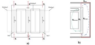
Table 1 Typical zero sequence impedance values for two-winding transformers with different cores according to IEC 60076-8 standard
| Impedance % | ||||||
|---|---|---|---|---|---|---|
| Winding symbol | Excited winding, 3-limb core | Excited winding, 5-limb core | ||||
| (1) | (2) | (1) | (2) | (1) | (2) | |
| YN | Y | ≈ 50 | - | ≈ 104 | - | |
| Y | YN | - | ≈ 60 | - | ≈ 104 | |
| YN | YN | a1z12 | a2z12 | Z12 | Z12 | |
| YN | D | a1z12 | - | Z12 | - | |
| D | YN | - | a2z12 | - | Z12 | |
Note:
z12 |
is short-circuit positive-sequence impedance |
a1 and a2 |
are multiplying factors in the range: 0.8 < a1 < a2< 1 |
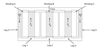
In a five-limb core transformer, the zero-sequence flux behavior is different because the unwound outer columns allow the flux to return, and thus the flux can be canceled (figure 3). Zero sequence flux cancellation in the columns results in lower zero sequence reluctance and high magnetizing impedance [5, 9, 10, 11].
The differences in the behavior of the zero sequence fluxes shown in figures 2 and 3, allow us to understand that there are notable differences in the zero sequence impedance, therefore, if they are not taken into account in the short-circuit calculations, this leads to significant errors in the values of the currents. Because of this, it has become necessary to search for methods to find the real values of the zero-sequence impedances [12].
According to the reference [11], the IEC 60076-8 standard provides a zero sequence impedance circuit in correspondence with the design of the magnetic core of the transformer (figure 4 a), shows the mathematical model of the five-limb core, where Z0 represents the zero-sequence leakage impedance provided by the manufacturer. Moreover, figure 4 b), shows the three-limb core model, where Zm represents the magnetizing impedance, while the zero-sequence leakage impedance (Z0) is divided into ZA and ZB.
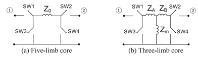
Fig. 4 General series and shunt switch models for the zero-sequence circuit of two-winding transformer, a) Five-limb core, b) Three-limb core [11]
The use of switches (SW1, SW2, SW3, and SW4) in figure 4, allows the zero sequence impedances to be represented according to the different winding connections. In the case of the grounded wye connection, two switches were used in series (SW1 and SW2), while in the case of the delta connection, two shunt switches were used (SW3 and SW4). These configurations allow the zero-sequence impedance equivalent circuits to be designed according to the connection of the windings (figure 5), [11].
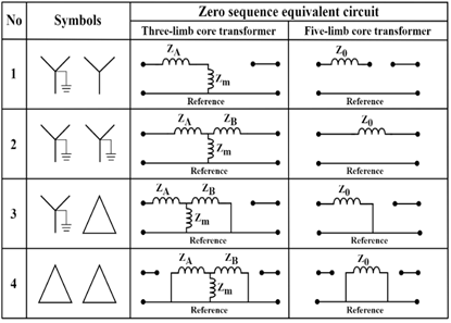
Fig. 5 Zero-sequence equivalent circuit according to winding connections - author’s elaboration from [11]
The equivalent circuits shown in the figure above reflect the importance of knowing the type of three-phase transformer core in short-circuit studies for the occurrence of asymmetrical faults. In the case of zero-sequence networks in a five-limb cores transformer, these are the same as those shown in figure 1, while in the case of a three-limb cores transformer, the behavior is completely different. These considerations call for the attention of specialists in the field of short-circuit studies before the implementation of electrical protection systems in networks, due to the possible occurrence of peculiar phenomena such as those that will be dealt with in the following sections.
Case study 1: The transformer as a short-circuit source
For many specialists and technicians involved in the settings of electrical protection, it is very difficult to understand that under very peculiar circumstances the transformer can behave as a short-circuit source due to its zero-sequence impedance. This case is part of the concept of the infeed effect that can manifest itself in shunted transmission line and affect the impedance measurement in the distance protection, which can bring problems to the stability of the power system [13, 14, 15, 16, 17].
The infeed effect is one of the many phenomena that affect the operation of distance protection, which can not be used as the main protection on transmission lines [14, 18, 19, 20]. In the case of transformers that can be left in no load conditions on shunt lines, the intermediate source phenomenon manifests itself only in the occurrence of single-phase and two-phase ground faults. This phenomenon causes uncertainty among technicians and specialists, who may not take it into account and make significant errors in the protection settings.
To analyze the phenomenon of the intermediate source in shunted lines, we will use the diagrams in figure 6, where we can see an equivalent of the power system with a shunted transmission line, while on bus 2 of the shunt is connected a transformer Yg∆ that is not connected to the load. The absence of the connected load allows us to disregard the pre-fault state in the transformer, and therefore the observation of the phenomenon will be more effective.
The occurrence of a single-phase or two-phase short-circuit to ground causes the short-circuit current ISC to present a contribution not only from the equivalent system (IS) but also from the unloaded transformer (IT), figure 6 b). This behavior is irregular because it only occurs in asymmetrical faults involving ground, in comparison with the other faults where the phenomenon is non-existent. The behavior of the short-circuit currents can be analyzed in detail in the sequence circuits of a single-phase fault on bus 3. See figure 6 c).
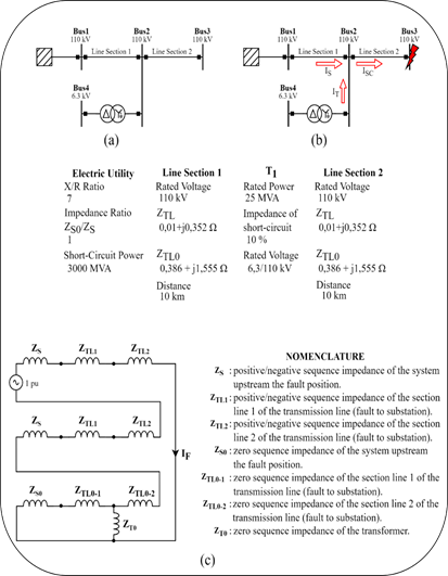
Fig. 6 Case 1 Diagrams, a) Diagram of lines in shunt with a transformer, b) Current paths to the short-circuit onbus 3, c)Sequence networks for a single-phase ground fault on bus 3
The analysis of the sequence networks in figure 6 c), shows that the transformer appears only in the zero-sequence diagram, which means that the zero-sequence impedance is responsible for the IT current. This phenomenon reveals that the transformer's contribution to the fault is zero-sequence; demonstrating that for two-phase and three-phase short circuits the transformer will not behave as a short-circuit source.
Case study 2: Transformer YYg at single-phase to ground faults
One of the uncommon connection groups in the analysis of asymmetrical ground faults is the YYg connection of the three-phase two-winding transformer. This connection group did not represent any interest for the specialists in electrical protection because the zero-sequence network was reduced to the equivalent circuit of figure 1, where the zero-sequence impedance did not participate in the ground fault.
At present, with this connection important care must be taken because the zero sequence network does not always behave as in figure 1, due to the type of transformer core. If the YYg transformer core is a five-limb core the zero sequence impedance can be neglected in the analysis of single-phase to ground faults, whereas in the case of a three-limb core, the zero sequence impedance cannot be neglected.
Figure 7, consisting of an equivalent power system in series with a transformer T1, will serve as an example for the explanation of the phenomenon. In conjunction with figure 7 a) and b), figure 7 c) and d), also shows the behavior of the sequence circuits in different types of cores in the event of a single-phase short-circuit to ground on bus 2.
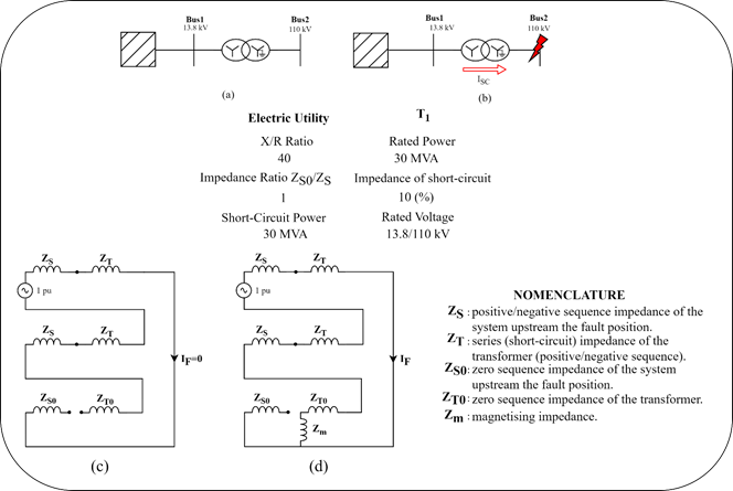
Fig.7 Case 2 Diagrams, a) Equivalent system in series with a transformer with connection group YYg, b) Direction of the short-circuit current in the event of a single-phase fault on bus 2, c) sequence network for a five-limb core transformer in the event of a single-phase short-circuit on bus 2, d) sequence network for a three-limb core transformer in the event of a single-phase short-circuit on bus 2
The analysis of figure 7, allows us to understand that the sequence networks are different depending on the transformer core. The occurrence of a single phase to ground fault on the grounded wye side can have a zero sequence current contribution and therefore an overcurrent protection could be used in the neutral of the transformer. Moreover,the differences in the behavior of zero sequence impedances in the presence of single-phase ground faults in YYg transformers draw the attention of protection specialists to the need for knowledge of the type of core to be able to correctly adjust the protection devices.
Results and discussion
To validate the phenomena explained above, simulations were carried out using MATLAB (mathematical software with academic licence number 41037228). The representation of the scenarios was made using the real values exposed in case studies 1 and 2, where the events of the different short circuits validate the issues raised in the Materials and Methods section.
Case study 1
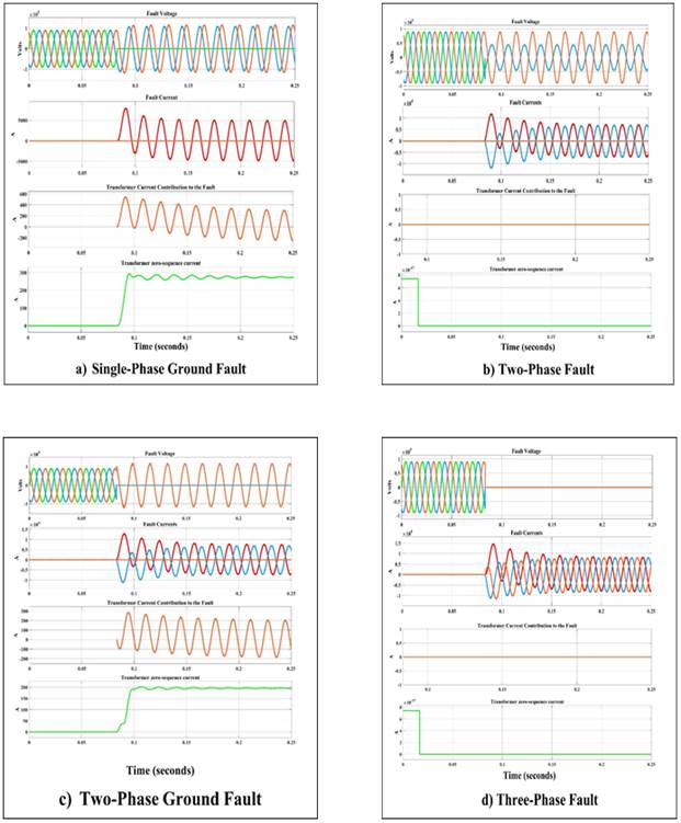
The results of the simulations for case study 1 are shown in figure 8, where the plots of voltage, short-circuit current, transformer short-circuit current contribution and transformer zero-sequence current are shown. The simulations were carried out for four types of faults where single-phase and two-phase ground faults being the most significant.
figure 8, shows that the transformer does not contribute to the zero-sequence current for three-phase and two-phase faults, demonstrating that this phenomenon occurs only for faults involving zero-sequence current. The contribution of the transformer to the short-circuit current is a special case of the infeed effect, showing that the transformer can behave as a short-circuit source in the presence of shunt lines.
Case study 2
figure 9 a) and figure 9 b)), show the results of case study 2, showing the transformer voltage, short-circuit current, and zero sequence current plots. The simulations were realized for single-phase ground faults to analyze the behavior of three-phase transformers with two windings but with different cores.
The figure 9 a), shows how, in the event of a single-phase short-circuit to ground, the transformer with a five-limb type core, the zero sequence current contribution is almost negligible, which means that the current at the short-circuit point is zero. This behavior is because the zero-sequence flux is cancelled at the transformer core and therefore the zero-sequence network can be represented as in figure 1.
In the case of figure 9 b), the response of the transformer to the occurrence of a single-phase short-circuit to ground is different from that of figure 9 a), because the three-limb core transformer brings zero-sequence current to the fault. This phenomenon demonstrates that short-circuit studies must take into account the type of transformer core which can influence the value of the single-phase short-circuit current to ground, and also opens up the possibility of applications near generating sets where single-phase ground faults can be detected by installing an overcurrent relay in the neutral of a YYg transformer with a three-limb core.

Conclusions
The analysis of the zero-sequence impedance in three-phase transformers depends on the connection group and the type of core. In the case of transformers with five-limbed cores, the zero-sequence impedance network behaves according to the traditional method found in the classical literature, while in the case of a transformer with a three-limbed core, the zero-sequence network behaves differently due to the influence of the magnetizing impedance and the zero-sequence flux that does not cancel in the outer columns of the core.
Moreover, the phenomenon of the transformer as a short-circuit source is a special case of the infeed effect that can occur in shunted transmission line. This case can only be understood by analyzing the zero-sequence impedance network of the transformer, since it only manifests itself for asymmetrical short-circuits in the presence of ground, whereas this phenomenon does not occur for three-phase and two-phase faults.
The YYg connection of a three-phase transformer can be used to detect ground faults if the transformer core is of the three-limb type, unlike the case of the five-limb core, which does not allow the fault to be detected because the zero-sequence impedance network is open and does not allow the zero-sequence current to flow. This peculiar phenomenon must be analyzed in detail by electrical protection specialists who, in some circuits, must take into account the structure of the transformer core, not only the connection group, in order to make the correct settings of the protection devices.

