SciELO - Scientific Electronic Library Online

 
vol.40 issue1Wireless Electronic System for Invalid Persons using Android devicesAnalysis of SFN gain behavior for DTMB author indexsubject indexarticles search
Home Pagealphabetic serial listing  

My SciELO

Services on Demand

Journal

Article

Indicators

  • Have no cited articlesCited by SciELO

Related links

  • Have no similar articlesSimilars in SciELO

Share


Ingeniería Electrónica, Automática y Comunicaciones

On-line version ISSN 1815-5928

EAC vol.40 no.1 La Habana Jan.-Apr. 2019


Artículo Original

Self-Interference Cancellation in MIMO Full-Duplex Transceivers

Cancelación de Auto-Interferencia en Transceptores MIMO Full Dúplex

Souleymane Diakité1 

Francisco Marante Rizo1 

1Universidad Tecnológica de La Habana José Antonio Echeverría, La Habana, Cuba

ABSTRACT

The transceiver nonlinearities have recently been shown to limit the performance of in-band FD (Full-Duplex) devices. In this article, detailed modeling and mitigation algorithms of more critical of these nonlinearities, in order to obtain better SI (Self-Interference) cancellation performance are presented. In the transmitter side, we propose to applied DPD (Digital Predistortion) to both, transmit and cancellation chains in order to obtain output signals free from nonlinearities of RF components, and crosstalk effects, which allow better RF cancellation. In the receiver side, the nonlinearities of RF components are modeled and the residual SI that will experiment these nonlinearities will be mitigated by digital cancellation. Our proposed method, ''DPD cancellation'', provides one of the simple signal models of SI signal that takes into account more of RF components nonlinearities, and crosstalk effect between the transmitter chains in MIMO-FD (Multiple Input Multiple Output Full-Duplex) transceivers. In this paper, the effect of the phase noise has been considered in the transceiver architecture, which can be minimized by using the same local oscillator for transmitter, cancellation and receiver chains. The simulation results show that, our method, DPD cancellation, provides better SINR (Signal to Interference plus Noise Ratio) at the input of the detector at the receiver, when compared to others methods in literature. In this way, it can be considered as one of the promising methods for the practical implementation of FD transmission in the future wireless systems.

Keywords: Full-Duplex; Self-Interference; Cancellation; Digital Predistortion; MIMO

RESUMEN

Recientemente se ha demostrado que las no-linealidades del transceptor imponen limitaciones en el rendimiento de los dispositivos FD (Full-Dúplex). En este artículo, elaboramos en detalle modelos y algoritmos de mitigación de las más críticas de estas no-linealidades con el objetivo de obtener mayor nivel de cancelación de la señal de auto-interferencia. Para el transmisor, proponemos de aplicar la predistorsión digital (DPD: Digital Predistortion) tanto en la cadena de transmisión como en la cadena de cancelación para obtener una salida sin no-linealidades de los componentes RF y sin efectos crosstalk, lo que permite mayor cancelación analógica RF. Para el receptor, las no-linealidades de los componentes RF son modeladas y la señal de auto-interferencia residual que experimentará esas no-linealidades será mitigada por la cancelación digital. Nuestro método,‘’DPD Cancelación’’ ofrece uno de los modelos más simples de la señal de auto-interferencia que toma en cuenta la mayor parte de las no-linealidades de los componentes RF y efectos de las interferencias (crosstalk) que ocurren entre transmisores de los transceptores MIMO-FD (Multiple Input Multiple Output Full-Dúplex). En ese trabajo, el efecto del ruido de fase del mezclador ha sido considerado en la arquitectura del transceptor, el cual se puede minimizar utilizando el mismo oscilador local para el transmisor, cadena de cancelación y el receptor. Los resultados de la simulación muestran que “DPD cancelación” permite obtener mayores valores de la relación señal interferencia más ruido (SINR) a la entrada del detector en el receptor, cuando se compara con otros métodos existentes en la literatura. Por lo que ese algoritmo puede ser considerado como uno de los métodos prometedores para la implementación práctica de la transmisión FD en los futuros sistemas inalámbricos.

Palabras claves: Full-Dúplex; Auto-Interferencia; Cancelación; Predistorsión Digital; MIMO

1.- INTRODUCTION

The exponential evolution in mobile data traffic demands a spectrum and power efficient wireless transceiver which is capable to keep out this growth [1]. One of the most promising techniques for these requirements is FD (full-duplex) communication, where transmission and reception can occur simultaneously in the same frequency band [2-6]. The FD technique can further improve the spectral efficiency of the next generation wireless systems, such as the 5G network [7]. It can also boost or double the throughput of the conventional HD (Half-Duplex) [4]. Doubling throughput is of course a desirable achievement, but the challenge lies in attaining FD communication within the same spectrum is challenging. Especially the challenge is managing the SI (Self-Interference) that occurs from the transmitter to the receiver [4,8-11]. Transmitter non-linearities, in particular those introduced by the RF PA (Power Amplifier), have a significant impact on the SI cancellation in full-duplex systems [2]. The nonlinear distortions introduced by non-ideal hardware components remain, and must be removed in the digital domain [2].The nonlinearities produced by the DAC (Digital to Analo Converter) and phase noise were omitted in the signal model in [7]. The phase noise must be considered in FD transceivers utilizing OFDM to minimize its effect on the SI cancellation performance [12]. Its effect can be reduced by sharing the same local oscillator between the transmitter and receiver chains [13,14].

To achieve the benefits of FD technique, each receiver needs to effectively cancel the SI from its own transmitted signal [15]. In literature, there are two main methods for SI mitigation: passive suppression and active cancellation [1,16]. In passive suppression technique, the SI is blocked before it passed through recover circuitry. In case of active cancellation technique, the unwanted signals are removed by using analog and digital cancellation [1]. Active cancellation methods use an extra transmitter to create the destructive SI cancellation [6]. Passive suppression can be implemented as an integrated part of the antenna sub-system to increase the transmitter-receiver isolation [10,17]. Active SI cancellation technique is categorized into two types: RF cancellation stage is introduced to suppress the strong SI before the LNA (Low Noise Amplifier) and the ADC (Analog to Digital Converter) in order to prevent possible LNA /ADC overlapping, the digital cancellation stage, after the ADC reduces further the residual SI to a sufficient low level required for proper signal detection [15].The recent development in the area of Massive MIMO allows deployment of hundreds of antennas at the eNodB [18]. It is necessary to model the crosstalk, between transmitter chains in MIMO configuration, otherwise the accuracy of the regenerated SI signal is not sufficiently high [7]. The practical implementation of the FD techniques requires the strong self-interference signal to be suppressed, ideally to the noise-floor, as any residual SI will reduce the signal-to-noise ratio of the incoming desired signal [2].The PA operating at higher transmission powers (outside the linear region of the power amplifiers) was observed to introduce a significant ‘non-cancellable’ residual component [2,19]. In general, for known I/Q imbalance and PA distortion characteristics, the efficient DPD (Digital Predistortion) can be obtained [20]. Applying DPD to the baseband signal, the resulting transmit signal should have significantly reduced nonlinear components, which in turn would allow simpler cancellation models to be used. The cancellation chain can also be predistorted to further compensate for any residual nonlinear components still present in the transmitted signal [2]. Predistorting for all transmitters RF components nonlinearities requires us to find the inverse of the signal model corresponding to theses nonlinearities. While the inverse of a memory polynomial is also a memory polynomial, explicitly inverting the model is challenging [2,20,21]. In the ideal case, when the predistorted signal is applied as an input to the nonlinear component, the output will be free of nonlinear distortion. The DPD requires finding a suitable model for the inverse of the signal model corresponding to the cascaded nonlinear RF components such as DAC (Digital to Analog Converter), IQ-mixer, PA and nonlinear crosstalk effect.

As the contributions in this paper, we propose a new SI cancellation method, called ‘’DPD cancellation’’, where digital predistortion and SI cancellation algorithm are jointly applied. We will first model the SI signal by taking into account the nonlinearities of all transmitter RF components, and nonlinear crosstalk between transmitter chains in MIMO-FD transceivers. Then this signal model will be used to obtain the DPD coefficients. Also, we will model the nonlinearities of the receiver RF components in order to apply digital cancellation using the obtained signal model to remove the residual SI.

We will finally test and analyze the performance of our SI cancellation method. The results will be compared with others methods in literature.

This paper is organized as follows: Section 1: Introduction, Section 2: System Model, Section3 : Signal Model, Section 4: Digital Predistortion for all Hardware Impairments, Section 5: Self-Interference Cancellation, Section 6: Numerical Results and Analysis, finally Section 7 presents the Conclusions.

2.- SYSTEM MODEL

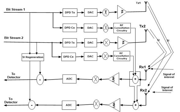
In this paper, we will consider MIMO-FD system in Figure 1 where two transceivers can transmit and receive simultaneously in the same frequency band. Each transceiver must be capable to cancel out the SI signal produced by its own transmission. The SI must be attenuated below the noise floor. To this end, we will apply DPD to linearize the transmit signal, which can minimize the nonlinearities of the transmit signal. Furthermore, the cancellation chain itself also can introduce nonlinearities, which arise from the internal amplifiers in the RF front-end [2]. To take into account these nonlinearities, DPD is applied at both, transmit and cancellation chains as proposed in [2]. Particularly, in this paper, DPD is applied to all RF components such as DAC, IQ-mixer, and PA, so that the transmit signal will be linear. Also the Digital Predistortion coefficients take into account the effect of nonlinear crosstalk. In the cancellation chain we incorporate an RF cancellation circuitry to take into account (by sounding the transmit and cancellation chains) the attenuation, delay, and multipath fading effect that will experiment the transmit signal between the transmitter j and receiver i as depicted in Figure 1.

At the receiver side, analog cancellation is first applied to prevent the receiver RF components saturation, such as LNA and ADC. After analog cancellation, digital cancellation is applied to further cancel the residual nonlinear SI components in the digital baseband domain. In this paper, to model the predistortion coefficients, we consider the DAC nonlinearities, the IQ imbalance between the direct and image component introduced by the mixers, the PA nonlinearities, and the crosstalk between transmitter chains before the PA. The phase noise is considered in the system architecture by using the same mixer for transmit, cancelation and receiver chains, which can reduce the effect of the phase noise [2,14,21]. The transmitter and cancellation predistortion coefficients are computed sequentially by sounding the channels using a randomly generated OFDM training signal [2].

Figure 1 Proposed DPD Cancellation Architecture in 2x2 MIMO-FD transceiver 

3.- SIGNAL MODEL

The DAC nonlinearities can be modeled in the baseband representation of the baseband signal using Taylor’s series expansion as [21]

xjDAC(n)=k=1kmaxakRe{xj(n)}k+jk=1kmaxbkIm{xj(n)}k (1)

Where ak and bk are the nonlinear coefficients for I- and Q- DACs, respectively. The expansion is truncated after Kmax terms.

In the baseband, the impact of the IQ imbalance can be modeled as an additional complex conjugate term as [21-23]

xjIQ(n)=β1,jxjDAC(n)+β2,jxjDAC*(n) (2)

Where β1,j and β2,j are the coefficients that can be derived from the amplitude and phase difference between the I- and Q- mixers. Then β1,j=12(1+gjejφj) , and β2,j=12(1gjejφj) , where gj and φj are the gain and phase imbalance parameter of the transmitter j. Notice that for any practical transmitter front-end |β1,j||β2,j| . The strength of the induced I/Q image component, represented by the conjugated signal term in (2), is typically characterized with the Image Rejection Ratio (IRR) as 10 log10(|β1,j|2/|β2,j|2) [22]. The Image Rejection Ratio (IRR) can reach a rather high level, so the image component can be neglected [3]. The crosstalk effect of the transmitter i under transmitter j (before the PA in MIMO transceivers) can be modeled as [7]

xj,in(n)=i=1NtαijxiIQ(n)=i=1Ntαij(β1,jxiDAC(n)+β2,jxiDAC*(n)) (3)

Where αij is the crosstalk coefficient between the ith and jth transmitter chains, and αjj=1j . The crosstalk occurring before the PA, each PA input signal is in fact a linear combination of all the different transmit signals [7]. As mentioned above, the image rejection ratio (IRR) of the devices can reach a rather high level, so the image component can be neglected [3]. Thus (3) can be written as:

xj,in(n)=i=1Ntα1,ijxiDAC(n) (4)

Where α1,ij=αijβ1,j .

The PA nonlinearities can be modeled as [1,7,20-22,24-26]

xjPA(n)=p=1poddPm=0Mhp,j(m)ψp(xj,in(nm)) (5)

Where hp,j is the FIR (Finite Impulse Response) filter impulse response of the PH (Parallel Hammerstein) branches for transmitter j, M and P denote the memory depth and nonlinearity order of the PH model, respectively. The basis functions are defined as:

ψp(x(n))=x(n)|x(n)|P-1=x(n)P+12x*(n)P12 (6)

Substituting (4) and (6) into (5) gives

xjPA(n)=p=1poddPm=0Mi=1Nthp,j(m)[α1,ijxiDAC(nm)]p+12[α*1,ijxiDAC*(nm)]p12 (7)

=p=1poddPm=0Mi=1Nth˜p,j(m)[xiDAC(nm)]p+12[xiDAC*(nm)]p12

Where h˜p,j(m)=hp,j(m)α^1,i , and α^1,i=(α1,ij)p+12(α*1,ij)p12

Then (7) can be rewritten as:

xjPA(n)=p=1poddPm=0Mi=1Nth˜p,j(m)xiDAC(nm)|xiDAC(nm)|p-1 (8)

This is the signal model in (8) contents all RF components impairments and nonlinear crosstalk effects between the transmitter chains. It will be used to find the predistortion coefficients, to linearize the transmit signal, which can minimize the effect of these nonlinearities on the SI cancellation performance at the receiver.

4.- DIGITAL PREDISTORTION OF ALL HARDWARE IMPAIRMENTS

In this section we outline the application of the DPD to the signal model in (8) corresponding to all transmitters RF components nonlinearities and nonlinear crosstalk signal model. The basic idea behind DPD is to compensate for the nonlinear distortion introduced by the RF components by appropriately distorting the baseband signal as [2,25,27].

In this paper, we follow the approach outlined in [2], and [25]. Figure 2 shows how a baseband signal, u(n), is predistorted before passing through the RF components. In the ideal case, when the predistorted signal, x(n), is applied as an input, y(n) will simply be u(n), and free of nonlinear distortion. Predistorting for all RF components requires us to find the inverse of (8), since it contains all nonlinearities of transmitter RF components. Inverting the signal model in (8) is challenging. By applying (8) we can model the inverse of (8), the output, y(n) is used to predict the input, x(n) as depicted in Figure 2, where y(n) is the output signal of “All RF Components and Crosstalk” circuit, and x(n) is its input, also x(n) corresponds to the output signal of the predistortion circuit. As depicted in Figure 1 y(n) will be the input of DAC components. Furthermore Figure 2 shows how the predistortion coefficients are estimated from the inverse of all RF components model. Once the system has converged, the coefficients are copied into the predistortion stage, which can then be run in open loop [2,21].

The KM predistortion coefficients, w, are estimated by transmitting a frame (containing N samples) of training data, x(n)=u(n) , for n=1,...,N . The received samples, y(n), are gathered into an Nx(KM) matrix, Y . Each column in Y corresponds to a specific coefficient in w , and is predistorted according to the basic function y(n-m)|y(n-m|p-1 , where m=0,1,...,M and p=1,3,...,P as defined in (5) and (8). The inverse model for (8) can then be expressed as x^=Yw . The estimation error is e=xx^ , and the least square solution that minimizes e2 is thus

w=(YHY)1YHx (9)

The transmitter and cancellation predistortion coefficients are computed sequentially by sounding the channels using a randomly generated OFDM signal. First, the transmit chain coefficients, wtx , are computed using (9), where Y is the received signal matrix, and x is the Nx1 vector of training samples. The cancellation chain coefficients wcx , could be computed similarly. We compute wcx by setting x in (9) to ytx , the signal obtained after predistorting the transmitter chain, as follows.

wcx=(YHY)1YHytx (10)

Figure 2 Application of DPD for all RF Impairments. Adapted from [2,25]. 

5.- SELF-INTERFERENCE CANCELLATION

To prevent the receiver RF components saturation, we must first apply analog cancellation (RF cancellation). Digital cancellation will remove the residual SI which will experiment the nonlinearities introduced by the hardware impairments. As depicted in Figure 1, for RF cancellation the analog circuitry can adjust attenuation, delay and phase between the transmitter and cancellation chains. We will model the receiver nonlinearities before applying digital cancellation algorithm to cancel out the SI from the total received signal.

5.1.- ANALOG CANCELLATION

For analog SI cancellation in this paper, we present an hybrid RF canceller using auxiliary transmitter with linear processing as [7]. Due to the DPD of the baseband signal, the transmitted signal, and analog cancellation reference signal, can be assumed linear. Thus, linear processing in the RF canceller is reasonable, since the RF canceller must only attenuate the SI such that the receiver is not saturated. The hardware complexity of this type of RF cancellation scheme scales with Nr instead of NtNr ( Nt and Nr denote respectively the number of transmit and receive antennas), and may prove to be more attractive with high number of antennas [7,22].

We denote the actual MIMO propagation channel impulse response from transmit antenna j to receive antenna i by Cij(l) , l=0,1,...,L , with L denoting the effective delay spread of the SI channel . The actual received SI signal at receive antenna i (i=1,2, …, Nr ) can be written as

zi(n)=j=1Ntl=0LCij(l)xjPA(nl) (11)

Note that p=1 , which indicates that this signal is linear.

We assume active cancellation, where the canceller structure utilizes an extra transmitter chains to up convert and subtract (after suitable gain, phase, and delay adjustments) estimated replicas of SI signals from the received signal at RF. The RF canceller can be either single-tap or multi-tap. Also, it can be easily shown that the cancellation signal is of similar form as the actual received SI signal. Thus the output signal of the RF canceller chain can be written as

zic(n)=j=1Ntl=0LhijRF(l)xj(nl) (12)

Where L is the number of taps in the RF canceller. Note again that in (12) p=1 , which indicates that this signal is linear.

The residual SI after RF cancellation can be expressed as

ri(n)=zi(n)zic(n)  =j=1Ntl=0max(L,L')[Cij(l)xjPA(nl)hijRF(l)xj(nl)] (13)

Note that the residual SI signal ri(n) is also linear.

Now, the nonlinearities introduced by the receiver RF components such as LNA, IQ-mixer, and ADC must be removed by the digital cancellation.

5.2.- DIGITAL CANCELLATION

Generally, digital SI cancellation is applied after analog cancellation to remove the nonlinearities introduced by hardware non-ideality. For digital cancellation in this paper, we will first estimate the residual SI channel, regenerate the residual SI signal, and then subtract it from the received signal.

We will consider the output signal of the RF canceller ri(n) , which is linear before passing through the receiver nonlinear components. This residual SI signal ri(n) will experience nonlinearities of RF components, such as LNA, IQ-mixer and ADC, at the receiver side. These nonlinearities must be taken into account in the cancellation algorithm to further reduce the effect of the residual SI. For brevity in this paper, we assume that ADC is linear component, such that we only take into account the LNA and IQ-mixer nonlinearities. The nonlinearity of LNA is modeled in [28] as (5), and the nonlinearity of the receiver IQ-mixer is modeled in the same manner as the transmitter IQ-mixer as (2).

The residual SI signal after the LNA can be written as

riLNA(n)=p=1poddPm=0Map,i(m)ψ(ri(nm) (14)

Where ap,i is the FIR filter impulse response of the PH branches for receiver i , M and P denote the memory depth and nonlinearity order of the PH model, respectively.

Incorporating the effect of the IQ imbalance of the IQ-mixer, we can rewrite

riIQ(n)=p=1poddPm=0Map,i^(m)ψ(rLNA(nm)) (15)

Where ap,i^(m)=β1rap,i(m) , where β1r is the gain of the direct component of the receiver IQ imbalance. Now, we can use the method proposed in [22] to adaptively estimate the residual SI channel, and then subtract the residual SI signal from the received signal. The total received signal at antenna i , including the residual SI signal, and signal of interest can be expressed as

yi(n)=riIQ(n)+si(n)+wi(n) (16)

Where yi(n) is the total received signal at antenna i , si(n) denotes the signal of interest, and wi(n) denotes receiver noise.

After N observations, yi(n) is expressed as yi(n)=[yi(n)yi(n+1)...yi(n+N1)]T , also si(n) , riIQ and wi(n) are defined in the same manner as yi(n) . The error vector is defined as

ei(n)=yi(n)r^iIQ(n) (17)

Where r^iIQ(n) denotes the nonlinear residual SI estimate, utilizing (15).

The nonlinear residual SI estimate r^iIQ(n) is expressed as

r^iIQ=[ψ1ψ2...ψNt][hTi1hi2T...hiNtT]T=ψa^^i (18)

Where a^^ij is the estimated channel from transmitter j to receiver i , and ψj is a (horizontal) concatenation of the matrices

ψj,P,'M'=(ψj,P,'M'(n)ψj,P,'M'(n1)ψj,P,'M'(nM'+1)ψj,P,'M'(n+1)ψj,P,'M'(n)ψj,P,'M'(nM'+2)ψj,P,'M'(n+N1)ψj,P,'M'(n+N2)ψj,P,'M'(n+NM')) (19)

Where ψj,P,'M'(n)=riLNA(n)|riLNA(n)|p-1 , with j=1,2,...,Nt , and p=1,2,...,P' .

The vector a^^ij is a (vertical) concatenation of the vectors

a^^p,ij=[a^^p,ij(0)a^^p,ij(1)...a^^p,ij(M1)]T (20)

Applying Least Square (LS) solution to the parameter vector ap,i^ which minimizes the power of the error vector ei , we can obtain an estimate of the residual SI channel as

a^^ij=argminei2=argminyiψap,i^2=(ψHψ)1ψHyi (21)

Now, with the residual SI channel estimate, we can regenerate the residual SI signal and subtract it form the received signal.

The output of the digital SI canceller at receive antenna i is then

si^(n)=yi(n)r^iIQ(n) (22)

Which corresponds to the detector input signal.

6.- NUMERICAL RESULTS AND ANALYSIS

In this section, we perform full waveform simulations of MIMO-FD transceiver with Matlab/Simulink to test and analyze our proposed method. The simulation parameters are given in Table 1, Table 2, and Table 3. The SI channel between transmit and receive antennas is modeled as a FIR filter. The power difference between the main component and the multipath components (K-factor) is 35.8 dB [29]. In the simulation, RF cancellation is implemented by subtracting the transmitted signal from the received signal with a small amplitude and phase mismatch such that the specified amount of total SI power reduction is obtained. For the simulation purpose in this paper, the PH model nonlinearity order is 5, and the filter lengths of the PH model are 10 for all the branches as [29].

The Figure-of-merit in this paper is the SINR (Signal-to-Interference plus Noise Ratio) of the detector input signal. As simulation results Figure 3 shows a comparison of SINR at input of the detector for different SI cancellation methods in literature. All the curves are plotted for the same passive suppression achieving 40 dB by antennas separation, and 30 dB achieved by RF cancellation. As depicted in Figure 3, for transmit power lower than 15 dBm, DPD Cancellation provides the best SINR when comparing to Nonlinear Cancellation method proposed in [29], Widely Cancellation method proposed in [30], Linear Cancellation and Joint Cancellation methods proposed in [22]. For high level of transmit power (more than 15 dBm), the PA will operate in its nonlinear region and some nonlinearities will be added to the signal of interest due to the non-ideality of the proposed Digital Predistorter, which can deteriorate the SINR. The SINR deterioration due to the high transmit power occurs with all existing digital cancellation methods. In this situation DPD Cancellation method is approximately comparable to Joint Cancellation method in terms of SINR, and is better than others methods in literature.

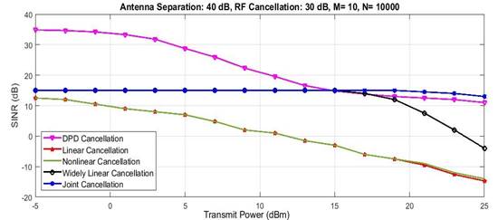
Figure 3 The SINR for different digital cancellation methods with respect to the overall transmit power, PH PA model. 

Table 1 Parameter for the relevant components of the transmitter and receiver chains 

Component Gain (dB) IP2 (dBm) IP3 (dBm) NF
PA (Tx) 27 - 13 5
LNA (Rx) 25 - 5 4.1
Mixer (Rx) 6 50 15 4

Table 2 System level and general parameters of the simulated 2x2 MIMO-FD transceiver 

Parameter value
SNR target 10 dB
Bandwidth 12.5 MHz
Rx noise Figure 4.1 dB
Rx sensitivity -88.9 dBm
Rx input power -83.9 dBm
Antenna separation 40 dB
RF cancellation 30 dB
PAPR 10 dB
IRR (Tx) 25 dB
IRR ( RX) 50 dB

Table 3 Parameter of the wave form simulator  

Parameters Value
Constellation 16-QAM
Number of subcarriers 64
Number of data subcarriers 48
Guard interval 16 samples
Sample length 15.625 ns
Symbol length 4 µs
Signal bandwidth 12.5 MHz
Oversampling factor 4

7.- CONCLUSIONS

For practical implementation of FD transmission technique in future wireless systems, a robust SI cancellation algorithm must be investigated. To this end, several investigations have been done. However most of these works do not take into account the nonlinearities of the RF components at both transmitter and receiver sides, and the crosstalk between transmitter chains in MIMO FD devices, which can deteriorate SI cancellation performance.

Therefore, we proposed a method that considers simultaneously these nonlinearities and crosstalk effect in the signal model and algorithm based on predistortion of transmit baseband signal, to improve the SI cancellation performance. The simulation results show that, DPD cancellation provides better levels of SINR at the input of detector at the receiver, when compared to others methods in literature.

Our method allows simplification of SI signal model, which can be very challenging when considering jointly hardware nonlinearities and crosstalk effect in MIMO FD transceivers.

In this paper, we have considered MIMO FD 2x2 transceivers, further investigations are needed to apply the same algorithm to massive MIMO FD scenario where 5G network devices size would be considered.

REFERENCES

1. Sekhar JS, Vijay EV. All-Digital Self-Interference Cancellation technique for MIMO Full-Duplex Systems. International Journal for Computer Applications. 2016;148(10):13-8. [ Links ]

2. Austin AC, Stimming AB, and Burg AP. Digital Predistortion of Power Amplifier Non-Linearities for Full-Duplex Tranceivers. 2016 IEEE 17th International Workshop on Signal Processing Advances in Wireless Communications (SPAWC), Edinburgh, UK, July 2016;6563-7. [ Links ]

3. Li J, Zhang H, and Fan F. Digital Self-Interference Cancellation Based on Independent Component Analysis for Co-Time Co-frequency Full-Duplex Communication Systems. IEEE Access. 2017;5:10222-31. [ Links ]

4. Chung M, Sim MS, Kim DK, Chae CB. Compact Full Duplex MIMO Radios In D2D underlaid Cellular Networks: From System Design to Prototype Results. IEEE Access, Recent Advances in Full-Duplex Radios and Networks. 2017;5:16601-17. [ Links ]

5. Riihonen T, Werner S, Wichman R. Comparison of Full-Duplex and Half-Duplex Modes with a Fixed Amplify-and-Forward Relay. 2009 IEEE Wireless Communications and Networking Conference, Budapest, Hungary, May 2009;13-7. [ Links ]

6. Mahmood N, Gilberto B, Leitão TF, Elgaard MP. On the Potential of Full Duplex Communication in 5G Small Cell Networks. IEEE 81st Vehicular Technology Conference (VTC Spring), Glasgow, UK, May 2015;1-5. [ Links ]

7. Korpi D, Anttila L, Valkama M. Nonlinear sel-interference cancellation in MIMO full-duplex tranceivers under crostalk. EURASIP journal on wireless Communications and Networking. 2017;2017(1):1-15. [ Links ]

8. Guimarães L, Bordim JL. A Full-duplex MAC tailored for 5G Wireless Networks. Wireless Communications and Mobile Computing, University of Brasília. 2018;2018:1-18. [ Links ]

9. Kim J, Kim WK, Kim JH. A New Full Duplex MAC Protocol to Solve the Asymmetric Transmission Time. 2015 IEEE Globecom Workshops (GC Wkshps), San Diego, CA, USA, December 2015. [ Links ]

10. Marasevic J, Chen T, Zhou J, Reiskarimian N, Krishnaswamy H, Zussman G. Full-Duplex Wireless: Algorithms and Rate Improvement Bounds for Integrated Circuit Implementations. Proceedings of the 2016 ACM (Association for Computing Machinery) HotWireless (invited), New York City, USA, October 2016;28-32. [ Links ]

11. Krier J, Akyildiz IF. Active Self-Interference Cancellation of Passband signals Using Gradient Descent. 2013 IEEE 24th Annual International Symposium on Personal, Indoor, and Mobile Radio Communications (PIMRC), London, UK, November 2013;1212-6. [ Links ]

12. Syrjäa V, Yamamoto K. Self-Interference Cancellation in Full-Duplex Radio Transceivers with Oscillator Phase Noise. IEEE European Wireless 2014; 20th European Wireless Conference, Barcelona, Spain, May 2014.832-7. [ Links ]

13. Ahmed E, Eltawil AM, Sabharwal A. Self-Interference Cancellation with Nonlinear Distortion Suppression for Full-Duplex Systems. 2013 Asilomar Conference on Signals, Systems and Computers Pacific Grove, CA, USA, November 2013;1190-203. [ Links ]

14. Masmoudi A. Self-Interference Cancellation for Full-Duplex Wireless Communications Systems. PhD Thesis, McGill University, Canada. 2016. [ Links ]

15. Masmoudi A, Le-Ngoc T. A Maximum-Likelihood Channel Estimator in MIMO Full-Duplex Systems. IEEE 80th Vehicular Technology Conference, Vancouver, BC, Canada September 2014;1-5. [ Links ]

16. Zhan Z. On Design Concept for Full-Duplex Based Flexible Radio Transceivers. PhD Thesis, Institut National des Sciences Appliquées de Lyon, France. 2014. [ Links ]

17. Ma J, Li GY, Zhang J, Kuze T, Iura I. A New Coupling Channel Estimator for Cross-Talk Cancellation at Wireless Relay Stations. 2009 IEEE Global Telecommunications Conference, Honolulu, USA December 2009;1-6. [ Links ]

18. Zheng K, Ou S, Yin X. Massive MIMO Channel Models: A Survey. International Journal of Antennas and Propagation. 2014;2014(3):1-10. [ Links ]

19. Bharadia D, McMilin E, Katti S. Full Duplex Radios. Conference on SIGCOMM, Hong Kong, China Augost 2013;43(4):375-86. [ Links ]

20. Antila L, Händel P, Valkama M. Joint Mitigation of Power Amplifier and I/Q Modulator Impairments in Broadband Direct-Conversion Transmitters. IEEE Transactions on Microwave Theory and Techniques. 2010;58( 4):730-9. [ Links ]

21. Austin A, Afisiadis O, Burg A. Digital Predistortion of Hardware Impairments for Full-Duplex Transceivers 2017 IEEE Global Conference on Signal and Information Processing (GlobalSIP), Montreal, QC, Canada, November 2017;878-82. [ Links ]

22. Antila L, Korpi D, Rodriguez EA, Wichman R, Valkama M. Modeling and Efficient Cancellation of Nonlinear Self-Interference in MIMO Full-Duplex Tranceivers. 2014 IEEE Globecom Workshops (GC Wkshps), Austin, TX, USA, December 2014;777-83. [ Links ]

23. Bozic M. Joint compensation of I/Q impairments and PA nonlinearity in mobile broadband wireless transmitters. PhD Thesis, University of Westminster London, United Kingdom. 2016. [ Links ]

24. Korpi D, Choi YS, Huusari T, Antila L,Talwar S, Valkama M. Adaptative Nonlinear Digital Self-Interference Cancellation for Mobile Inband Full-Duplex Radio: Algorithms and RF Measurements. 2015 IEEE Global Communications Conference (GLOBECOM), San Diego, CA, USA, December 2015;1-7. [ Links ]

25. Morgan D, Ma Z, Kim J, Zierdt MG, Pastalan J. A Generalized Memory Polynomial Model for Digital Predistortion of RF Power Amplifiers. IEEE Transactions on Signal Processing. 2006;54(10):3852-60. [ Links ]

26. Ding L, Zhou GT, Morgan DR, Ma Z, Kenney JS, Kim J, Giardina CR. A Robust Digital Baseband Predistorter Contructed Using Memory Polynomials. IEEE Transactions on Communications. 2004;52(1):159-65. [ Links ]

27. Gregorio F, Cousseau J, Werner S, Riihonen T, Wichman R. Power amplifier linearization technique with IQ imbalance and crosstalk compensation for broadband MIMO-OFDM transmitters. EURASIP Journal on Advances in Signal Processing. 2011;2011(19):1-15. [ Links ]

28. Marttila J, Allén M, Kosunen M, Ryynänen J, Valkama M. Reference Receiver Enhanced Digital Linearization of Wideband Direct-Conversion Receivers. IEEE Transaction on Microwave and Theory and Techniques. 2017; 65(2):1-14. [ Links ]

29. Antila L, Korpi D, Syrjälä V, Valkama M. Cancellation of Power Amplifier Induced Nonlinear Self-Interference in Full-Duplex Transceivers. 2013 Asilomar Conference on Signals, Systems and Computers, Pacific Grove, CA, USA, November 2013;1193-8. [ Links ]

30. Korpi D, Lauri A, Syrjälä V, Valkama M. Widely Linear Digital Self-Interference Cancellation in Direct-Conversion Full-Duplex Trnsceiver. IEEE Journal on Selected Areas in Communications. 2014;32(9):1674-87. [ Links ]

Received: August 02, 2018; Accepted: November 08, 2018

Souleymane Diakité, Telecommunications Engineer, PhD student at ‘‘Universidad Tecnológica de La Habana CUJAE’’, Cuba, Assistant Professor at ‘‘Institut des Sciences Appliquées (ISA)’’, Mali. E-mail: souleymane.diakite@isamali.org

Francisco R. Marante Rizo, PhD degree in Telecommunications in 1986 at ‘‘Technical University of Praga’’, Member of Wireless Communications Group at ‘’Universidad Tecnológica de La Habana José Antonio Echeverría (CUJAE)’’, Cuba. E-mail: marante@tele.cujae.edu.cu

Creative Commons License This is an open-access article distributed under the terms of the Creative Commons Attribution License