


Mi SciELO
 Servicios personalizados
Servicios Personalizados
Articulo
 Inglés (pdf)
 Articulo en XML
 Referencias del artículo
 Enviar articulo por email
Indicadores
-
 Citado por SciELO
Links relacionados
-
 Similares en
SciELO
Similares en
SciELO
Compartir

 Permalink
Ingeniería Mecánica
versión On-line ISSN 1815-5944
Ingeniería Mecánica vol.17 no.3 La Habana sep.-dic. 2014
ORIGINAL ARTICLE
Validation of a smooth configuration surface for compact heat exchangers using a numerical method
Validación de la superficie de un intercambiador de calor compacto en configuración lisa utilizando un método numérico
José-L. Leiro-Garrido, Rubén Borrajo-Pérez, Juan-José González-Bayón, Nelson Reyes-Béquer
Instituto Superior Politécnico José Antonio Echeverría. Centro de Estudios de Tecnologías Energéticas Renovables. La Habana. Cuba
ABSTRACT
This work determines the thermo hydraulics behavior of smooth configuration surface for a compact heat exchanger by means of numerical simulation. The objective is to use the results as baseline for research in the enhancement of heat transfer and drag reduction, directed to reduce the energy consumption and diminish the environmental impact. The fin tube heat exchanger models described. The constraints used in the implementation of the equation solver are announced. The average heat transfer coefficient and pressure drop obtained from numerical simulation are compare to experimental results presented in literature for models with the same dimensions and configuration. A good agreement between numerical and experimental results is reached. Local mechanisms responsible for the heat transfer and pressure drop are detailed. The study is conducted inside the laminar regime for frontal velocities ranging between 0.5 and 6 m/s.
Keywords: compact heat exchanger, heat transfer coefficient, numerical simulation, pressure drop.
RESUMEN
Este trabajo determina el comportamiento termo hidráulico de una superficie perteneciente a un intercambiador de calor compacto en configuración lisa utilizando un método de simulación numérica. El objetivo es caracterizar la superficie para poder utilizarla como una referencia en las comparaciones con superficies de intercambio de calor intensificadas. Los datos obtenidos se utilizaran en la determinación de los valores relativos de intensificación de la transferencia de calor y el arrastre intentando reducir el consumo energético y su impacto ambiental. Se describe el modelo de intercambiador de calor con tubos aletados. Los resultados numéricos obtenidos presentan un buen ajuste con los valores experimentales. Los resultados del coeficiente de transferencia de calor global y la caída de presión son explicados a partir de las particularidades locales del campo de velocidad y temperatura. El estudio es conducido en régimen laminar con velocidades a la entrada del modelo entre 0.5 and 6 m/s.
Palabras claves: intercambiadores de calor compactos, coeficiente de transferencia de calor, simulación numérica, caída de presión.
INTRODUCTION
Compact heat exchangers are used intensively at industrial and domestic applications. Among its principal characteristic heat exchangers presents higher values of heat transfer area in a relative small volume. The enhancement of heat transfer in finned surfaces is critical to improve the overall performance of heat exchangers Lei, et al. [1]. Extended surface are added to tubes, generally in form of fins, with objective of improve the total heat transfer exchange. The fins in its basic configuration are smooth but several configurations have been created looking for a higher performance. The enhancement of heat transfer on the fin surface is reached using several physical mechanisms. An interrupted boundary layer is employed in offset fins configuration, while vortex generation is the solution when wavy fin are used. Vortex generators punched or attached on the fin are a promissory technique used for the enhancement of heat transfer on fin surface [2, 3]. A baseline in smooth configuration will be needed to comparing purposes with results obtained in heat transfer and drop pressure for enhanced configurations.
Not only circular tubes have been studied but also elliptical and oval tubes. Brauer a pud Webb [4] was the first investigating this kind of geometry and compare it to circular. Bordalo & Saboya [5] focused its work in the hydraulic performance of heat exchangers having one and two rows of elliptical tubes. Sohal and O´Brien [6] developed an experimental and numerical work where oval and circular tubes were investigated; they presented a local and an average film heat transfer coefficient for fin in smooth configuration. Focusing in elliptical tube Perez, et al. [7], have reported a group of four correlations, valid for isothermal fin, for j and f and smooth fin as a function of Reynolds number, rows number and tube pitches.
Rich [8] made a group of experiments with heat exchangers having four rows where the fin pitches and fin thickness were studied. He concluded that the fin pitch did not affect the heat transfer coefficient and friction factor Wang, et al. [9] reported about the same effect than the previous work. At the same time, they found the fin thickness without any significance on the Colburn and friction factor. Wang & Chi [10] revealed higher values of j and f when the fin pitch is smaller. They work with pin pitch ranging from 1,4 to 2.0 mm. The reason for these contradictory results could be the dissimilar geometries studied and the measurement uncertainness.
Numerical methods have become in a powerful tool in forecast of velocity and temperature field in compact heat exchanger with the objective of know its thermo hydraulics performance. Using this tool have been studied several geometries of tube. Chen, et al [11] compare the local numerical result of a heat exchanger having three rows of flat tubes with experimental results obtained by means of naphthalenes ublimation. The numerical method employed was able to reproduce the local Nusselts number in isothermal condition.
Different experimental techniques are used in compact heat exchanger analysis. Stasiek et al. [12] used liquid crystal thermography and particle image velocimetry. These are among the most precise tools to obtain temperature and velocity fields governing the thermal and hydraulic performance of heat exchangers.
The influence of several transversal pitches for one longitudinal pitch tube was studied in Burkov, et al. [13] for six rows of tubes. A higher heat transfer coefficient was found when transversal pitch is lower. The Reynolds numbers was in turbulent regime.
The heat transfer enhancement of compact heat exchanger is an important matter in the scientific literature at present. Experimental methods are expensive and difficult to be implemented. Numerical methods are being used for predictions of thermo hydraulics behavior of heat exchanger with enhancement technique implemented as in He, Y., et al [14]. In some cases, have been used combined enhancement techniques as in Huisseune, et al [15]. The combination have been considered as a new generations in the enhancement heat transfer area. Not only in compact heat exchangers but also in solar collector for air heating the enhancement heat transfer have been applied. Modifications of boundary layer created by natural convection and interrupted by means of vortex generators was the cause of enhancement heat transfer in this area as can be found in Bekele, et al. [16]
The confidence of both methods, experimental or numerical is high as was concluded in Biswas, et al [17]. However every researcher need establish its own numerical models prove it and validate it before begin to study geometries that are more complex and enhancement technique.
This work is about the numerical modeling of a compact heat exchanger having a row of circular tubes with air flowing outside the tubes in laminar regime. The objective is to validate the numerical model and the method employed, focusing the use of results as a baseline in future investigations related to the enhancement of heat transfer. A validated computational fluid dynamics model can provide flow and temperature field information at lower cost.
MATERIALS AND METHOD
The governing equations, which describe the physical phenomenon of the fluid inside the heat exchanger, are: the continuity, momentum, energy equations and the ideal gas equation of state as equations follow 1, 2, 3 and 4:
![]()
![]()
![]()
![]()
In the equations above u was reserved for velocity and x for coordinates. As subscript for its components and directions were used i and k. Was reserved K for thermal conductivity, cp is the isobaric specific heat and ρ is the density. In equation of state, the terms used are R for the gas constant of air, p, v and T are the pressure, specific volume and temperature respectively.
The validation of the numerical model by means of comparison with the published experimental result will be obtained applying the governing equations on the physical model of a heat exchanger. The selected physical model shall have exactly the same size than the model tested by Wang & Chi [10] having a row of circular tubes. The dimensions of this model are 19,05 mm for longitudinal pitch, 25,4 mm for transversal pitch, a fin pitch of 2,04 mm and a tube collar diameter of 8,51 mm. During the simulation was considered a symmetrical domain in the transversal direction. The figure 1 shows the plant and lateral views of the computational domain and its dimensions. The model was extended ten millimeters in the exit direction avoiding reversal flow and permitting an outflow boundary condition. The coordinate x is in the span wise direction and the y coordinate is the main flow direction. The flow channel is limited at top and the bottom by the two fins.
The channel height (coordinate z) is the characteristic dimension selected for Reynolds number determinations while the frontal was the selected velocity. A flow laminar, steady, incompressible, with constant properties and tridimensional was considered. A segregated model was employed and conjugate heat transfer in the region of contact solid-fluid was applied.
The operational conditions selected were: a constant temperature of the tube wall (276 K), the inflow having a constant temperature of 300 K and an atmospheric pressure equal to 101,325kPa. The velocity inlet was varied from 0.3 to 6 m/s where only velocity component in the y direction is possible. Additional boundary condition such an adiabatic wall for each fin edge in the front and back region were considered. The fin edge and laterals were considered symmetrical. A non-slip condition over every solid surface was applied. For the heat transfer coefficient calculate was selected an average temperature between the inlet temperature and a mass average temperature in the exit section.
The mesh was constructed in Gambit. The solution was first obtained for isothermal flow and then was added the energy equation for the final solution. During the solution were monitored the convergence of the scaled residual up to 10-7 for energy and 10-4 for momentum equations. Several mesh adaption processes were implemented refining the cells having higher values of gradient of velocity, temperature and surface heat transfer coefficient. During the adaption processes the surface heat transfer coefficient and the drop pressure was monitored until its values were unchanged.
RESULTS AND DISCUCCIONS
The results of the model simulation were processed and the average heat transfer coefficient (h) and the drop pressure ( p) through the model were obtained as was explained. In the figure 2, are presented the values of both, the mentioned parameters calculated by means of the present model and the experimental results published by Wang & Chi [10] as a function of the frontal velocity (Vfr).
The agreement between the experimental and the numerical values is high presenting almost a perfect match. The differences, in the worst cases, are ranging about 9 % for the heat transfer coefficient and 8 % for the drop pressure. These discrepancies are acceptable if the experimental uncertainty is considered. The authors consider validated the numerical model used here.
![Fig. 2. Experimental results of Wang & Chi [10] and numerical results of the present work](/img/revistas/im/v17n3/f0209314.jpg)
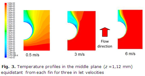
The variation of the frontal velocity produces an important effect on the heat transfer and pressure drop. Following in the figure 3 are presented three temperature profiles in the middle plane (z =1,12 mm) equidistant from each fin for the velocities corresponding with 0,5, 3 and 6 m/s. When the velocity of the flow is increasing can be noted how the temperature of the middle plane is approaching to the inlet temperature. Higher velocities produce an important convection instead of the governing conduction phenomenon manifested at lower velocities. When the flow is in laminar regime the only mechanism able to change the temperature of the successive adjacent fluid layer is the heat conduction.
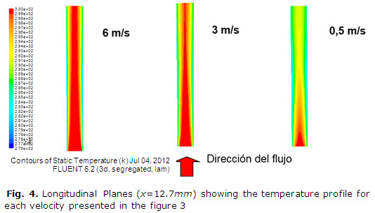
The boundary layer growing for the same velocities previously studied is shown in the figure 4. Can be noted how the models having the higher velocities is presenting a thinner thermal boundary layer while the model having lower velocity has a thicker thermal boundary layer cause of a lower energy transport by convection.
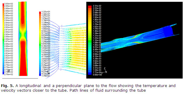
The previous explanation is, of course, for a longitudinal plane far from the tube and exactly in the middle point between two consecutive tubes. If a similar plane, closer to the tube will be show then the horseshoe vortices created in the front of the tube will have modified the flow structure. The presence of these vortices produces the mixing of the cold fluid, close to the fin, with the hottest fluid in the free stream. The mixing in addition to the thinner of the boundary layer, caused by the momentum transported to the fluid layers flowing close to the fin, are responsible for the improve of the heat transfer occurring when the velocity is augmented. The composition on figure 5 is showing a graphical explanation to the phenomenon mentioned before.
A longitudinal plane created in the near of the tube surface (x=4,8 mm) show the vortex effect on the perturbed area characterized by a green-yellow color. The velocity vectors, in blue color, close to the tube surface are showing perfectly the vortex formation. As confirmation of the vortex presence and the capacity of the model for capturing it are shown the path line of flow surrounding the tube. The view shown is longitudinal and the perpendicular to the figure is coincident with the radial direction from inside to outside of the tube
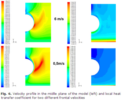
In the figure 6 is noted which are the two mechanisms responsible for the heat transfer in a compact heat exchanger having smooth fins. The first is the developing boundary layer on the inlet of the fin and the other the horseshoe vortex created in front of the tube. In the contours of velocity are noted the vortex presence and the effect of acceleration produced by the flow area reduction in the center of the model. Is significant the larger wake tube region presented in models with the lower velocity, because of the dislocating of the separation point of the boundary layer to a backward direction.
The Nusselt in the spanwise direction was calculated. A peak of heat transfer coefficient was obtained for every model in the inlet region, coinciding with the developing boundary layer. When the velocity inlet is higher a small peak begins to appear in front of the tube as can be observed in the figure 7. In the picture the location of the tube is indicated. Even for higher velocities, the maximum of the heat transfer coefficient is obtained in the leading edge of the fin.
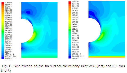
Finally in the figure 8 the skin friction on the fin surface was found with a behavior very similar to the shown for the heat transfer coefficient. Improve in heat transfer should be penalty with higher drop pressure in agreement with the Colburn's analogy as can be observed. The color scale of the skin friction is not the same for each graphic.

CONCLUSIONS
A baseline for future comparison of model having enhancement heat transfer techniques applied with model in smooth configuration is available now. The results were obtained by means of gradient mesh refinement avoiding a higher cell number produced when the cell size is diminished looking for a mesh independent solution.
The numerical model employed to simulate the heat and transfer performance of a compact heat exchanger having a fin tube was validated. The agreement between experimental and numerical was high, presenting almost a perfect match. The comparison was made using the average heat transfer coefficient and drop pressure through the model and the experimental result published in the scientific literature.
Dimensionless numbers were not employed because the compared models have similar dimensions. As expected, a correspondence between the skin friction and the values of the heat transfer coefficient was observed.
The mechanism responsible for the heat transfer in a compact heat exchanger with a row of tube having fin in smooth configuration were confirmed having the same phenomenology than the elucidated in the literature. Heat transfer coefficient integrated in the spanwise direction is presented, supporting the previous conclusion.
REFERENCES
1. Lei, Y., He, Y. y Tian, L. "Hydrodynamics and Heat Transfer Characteristics of a Novel Heat Exchanger with Delta-winglet Vortex Generators". Chemical Engineering Science. 2010, vol. 65, nº. 5, p. 1551-1562. ISSN 0009-2509. DOI 10.1016/j.ces.2009.10.017
2. Aider, J., Beaudoin, J. y Wesfreid, J. "Drag and Lift Reduction of a 3D Bluff-body using Active Vortex Generators". Experiments in Fluid. 2010, vol. 48, p. 771-789. ISSN 0723-4864. DOI 10.1007/s00348-009-0770-y
3. Henze, M., Wolfersdorf, J. V. y Weigand, B. "Flow and Heat Transfer Characteristics Behind Vortex Generators-A Benchmark Dataset". International Journal of Heat and Fluid Flow. 2011, vol. 32, nº. 1, p. 318-328. ISSN 0142-727X. DOI 10.1016/j.ijheatfluidflow.2010.07.005
4. Webb, R. L. Principles of Enhanced Heat Transfer. First ed. New York, USA: John Wiley & Sons, 1994. ISBN 100471577782.
5. Bordalo, S. y Saboya, F. E. "Pressure Drop Coefficient for Elliptical and Circular Sections in one, two and three-Row Arrangements of Plate Fin and Tube Heat Exchangers". Journal of Brazilian Society of Mechanical Science. 1999, vol. 21, nº. 4, p. 600-610. ISSN 1678-5878.
6. Sohal, M. S. y Obrien, J. E. "Improving Air-Cooled Condenser Performance Using Winglets and Oval Tubes in a Geothermal Power Plant". Geothermal Resources Council Transactions. 2001, vol. 25, p. 1-7. ISSN 0193-5933.
7. Perez, R. B., Yanagihara, J. I. y Bayón, J. G. "Thermal and Friction Drop Characteristic of Heat Exchangers with Elliptical Tubes and Smooth Fins". Ingeniería Mecánica. 2012, vol. 15, nº. 3, p. 243-253. ISSN 1815-5944.
8. Rich, D. G. "The Effect of Fin Spacing on the Heat Transfer and Friction Performance of Multirow, Smooth Plate Fin and Tube Heat Exchangers". ASHRAE Transactions. 1973, vol. 79, nº. 2, p. 135-145. ISSN 0001-2505.
9. Wang, C., Lee, W. y Sheu, W. A. "Comparative Study of Compact Enhanced Fin and Tube Heat Exchangers". International Journal of Heat and Mass Transfer. 2001, vol. 44, p. 3565-3573. ISSN 0017-9310.
10. Wang, C. y Chi, K. "Heat Transfer and Friction Characteristics of Plain Fin-and-tube Heat Exchangers, Part I: New Experimental Data". International Journal of Heat and Mass Transfer. 2000, vol. 43, p. 7-10. ISSN 0017-9310.
11. Chen, Y., Song, K. y Wang, L. "Comparisons of Local Experimental Results with Numerical Results of Heat Transfer Enhancement of a Flat Tube Bank Fin with Vortex Generators". Numerical Heat Transfer. Part A. 2009, vol. 55, p. 144-162. ISSN 1040-7782. DOI 10.1080/10407780802603204
12. Stasiek, J., Stasiek, A. y Mikielewicz, D. The use of Liquid Crystal Thermography and Particle Image Velocimetry in the Exploration of Heat Transfer Measurements. En: The 6th Symposium on Turbulence, Heat and Mass Transfer. Rome, Italy. 2010. p. 1-11. ISBN 978-1-56700-262-1.
13. Burkov, V. K., Medvedskii, V. P. y Kochegarova, I. Y. "Studies of Heat Transfer and Aerodynamics". Thermal engineering. 2010, vol. 57, nº. 3, p. 227-231. ISSN 0040-6015. DOI 10.1134/S0040601510030067
14. He, Y. L., Han, H. y Tao, W. "Numerical study of heat-transfer enhancement by punched winglet-type vortex generator arrays in fin-and-tube heat exchangers". International Journal of Heat and Mass Transfer. 2012, vol. 55, p. 5449-5458. ISSN 0017-9310. DOI 10.1016/j.ijheatmasstransfer.2012.04.059
15. Huisseune, H., Tjoen, C. y Dejaeger, P. "Performance Enhancement of a Louvered fin Heat Exchanger by Using Delta Winglet Vortex Generators". International Journal of Heat and Mass Transfer. 2013, vol. 56, p. 457-487. ISSN 0017-9310. DOI 10.1016/j.ijheatmasstransfer.2012.09.004
16. Bekele, A., Mishra, M. y Dutta, S. "Heat transfer augmentation in solar air heater using delta-shaped obstacles mounted on the absorber plate". International Journal of Sustainable Energy. 2013, vol. 32, nº. 1, p. 53-69. ISSN 1478-6451. DOI 10.1080/14786451.2011.598637
17. Biswas, G., Chattopadhyay, H. y Sinha, A. "Augmentation of Heat Transfer by Creation of Streamwise Longitudinal Vortices Using Vortex Generators". Heat Transfer Engineering. 2012, vol. 33, nº. 4-5, p. 406-424. ISSN 0145-7632. DOI 10.1080/01457632.2012.614150
Recibido: 6 de marzo de 2014.
Aceptado: 16 de junio de 2014.
José-L. Leiro-Garrido. Instituto Superior Politécnico José Antonio Echeverría. Centro de Estudios de Tecnologías Energéticas Renovables. La Habana. Cuba.
Correo electrónico:jleiro@mecamail.cujae.edu.cu
