


Meu SciELO
 Serviços customizados
Serviços Personalizados
Journal

Artigo
 Inglês (pdf)
 Artigo em XML
 Referências do artigo
 Enviar este artigo por email
Indicadores
-
 Citado por SciELO
Links relacionados
-
 Similares em
SciELO
Similares em
SciELO
Compartilhar

 Permalink
Ingeniería Mecánica
versão On-line ISSN 1815-5944
Ingeniería Mecánica vol.19 no.1 La Habana jan.-abr. 2016
ORIGINAL ARTICLE
Thermal hydraulic performance of a wavy fin having two row of circular tubes
Caracterización de una aleta ondulada con dos filas de tubos circulares
Rubén Borrajo-Pérez, Juan-José González-Bayón, Darían Reyes-Fernández-de-Bulnes
Instituto Superior Politécnico José Antonio Echeverría, Facultad de Ingeniería Mecánica. La Habana, Cuba
ABSTRACT
This paper is about the thermal and hydraulic characterization of a compact heat exchanger having two row of tubes and rectangular wavy fins. The dimension of the tubes and the fin are similar to the used in the air conditioning and refrigeration area. A numerical approach was used and the computational domain was implemented using symmetry and periodic condition. Were considered extended inlet and outlet section for accuracy. The numerical procedure ant its model were certified against published literature and a good match was found. The impinging flow on the fin surface was found responsible for the differences between the heat transferred at every side of the fin. The differences disappearing when the average value was calculated.
Key words: wavy fin, compact heat exchanger, numerical model, thermo-hydraulic behavior.
RESUMEN
Este trabajo trata sobre la caracterización térmica e hidráulica de un intercambiador de calor compacto con dos filas de tubos circulares y aletas onduladas rectangulares. Las dimensiones de los tubos y las aletas son similares a las usadas en el área de la climatización y la refrigeración. Se utilizó un abordaje numérico y el dominio computacional implementado se completó con condiciones de contorno de tipos simétrica y periódica. El dominio fue extendido en ambas direcciones del flujo para aumentar la precisión de los resultados. El procedimiento numérico y el modelo implementado fueron validados frente a valores publicados en la literatura con los cuales se obtuvo un buen ajuste. La incidencia del flujo sobre la superficie de la aleta fue encontrada responsable por las diferencias encontradas entre el comportamiento de ambos lados de la aleta. Las diferencias encontradas desaparecen cuando se considera el calor total transferido por la aleta.
Palabras claves: aleta ondulada, intercambiador de calor compacto, desempeño termo-hidraulico.
INTRODUCTION
Extended surface or fins are employed frequently to augment the heat transferred from tubes in heat exchangers. Every fin has its own design and many differences can be found when they are compared. The plate fin is the simplest and is considered the basic configuration. Prediction of pressure drop and heat transferred by a fin-tube heat exchanger constitute a hard and many times an expensive task. This is because exist a complex flow pattern when it is flowing through a heat exchanger channel between consecutive fins. Every modification of the basic geometry need to be investigated as a new one to obtain its thermal-hydraulic performance. Several models of wavy fins can be created only by modification of its main dimensions. The transversal and longitudinal pitches, tube diameter, fin spacing and angle of the wavy are magnitudes which determine the thermal performance and the pressure drop of a heat exchanger consist of tubes and wavy fins.
In 1996 Wang et al [1] carried out a study of convex louver fins and it was compared with, among others, a wavy fin. The Reynolds number based in the collar diameter ranged from 400 to 8000. This work had an experimental approach and the wavy fin studied had 25,4 mm and 1,05 mm as transversal and longitudinal pitches respectively. The model had two row of tubes and a fin pitch of 2,54 mm. The collar diameter was 10,06 mm. The pressure drop of the wavy fin was found comparable to the pressure drop of the others fins and higher than pressure drop of the plate fin.
On the other hand, the heat transfer data were presented as a multiplication of the fin efficacy by the average heat transfer coefficient (![]() ). The importance of this article is the experimental data presented, which can be used as a reference for validations.
). The importance of this article is the experimental data presented, which can be used as a reference for validations.
An extensive work of Wang et al. [2] was dedicated just to wavy fin. Two different configuration of wavy fin were considered. The fin pitch was varied and its effect on the heat transfer was analyzed. Was found a negligible effect of the fin edge corrugation in the studied geometries. An important result was the correlation, proposed for j and f and valid for the studied geometries. The general dimensions of this geometries were bigger than used in this work.
Fan et al [3] carried out another investigation considering wavy fin. A numerical approach and the Fluent software was selected for the calculations. Two dispositions of the computational domain were used, the first was the channel between two consecutive fin and the other was the fin in the middle of two half of a channel. A periodicity condition was considered in two coordinates. The objective was made an investigation to intend the substitution of a geometry having three row of inline wavy fin-tubes by a new enhancement geometries consisting of two rows of wavy fin-tubes using an enhancement technique. Several combined configurations of enhancement surface were tested and one of them was chosen as the best. The selected geometry was a combination of vortex generators and protruding strip. The result of heat transfer are presented using the heat transfer rate by the fin versus the frontal velocity. The new enhancement geometry save an important quantity of volume and material. The penalty of pressure drop was always considered and several geometries were not useful because of a high pressure drop.
Sadrul and Arafat [4] investigated wavy fin in the Reynolds numbers ranged from 1200 to 3000. They made a numerical study of heat exchangers with four rows of tube in line and staggered arrangement. The fin spacing, wavy angle and angle of the inlet flow were investigated. Finite elements method was applied and isothermal boundary condition at wall were imposed. The longitudinal and transversal pitches were varied and its effect on the heat transfer and pressure drop was analyzed. They used an efficiency index which was found having the best value always for the worst heat transfer condition. This result is indicating how the pressure drop is the mandatory magnitude in this kind of fin.
An interesting work where the fin spacing was varied from 0,4 to 4 mm was carried out by Glazar et al [5]. The paper was intended to determine the best value of fin pitch for every frontal velocity tested from 0,5 to 5 m/s when only the heat transferred is considered. The result were presented directly in average heat transfer coefficient and pressure drop. A numerical approach was carried out. The wavy fin studied had the same dimensions than used by Wang et al [1]. The domain was extended in the inlet and the outlet sections until seven times of its real size. The values of average heat transfer coefficient obtained were higher when compare to the values in the referenced paper (Wang et al [1]). Really, the values of h are almost similar in these papers but they were not presented in the same base. The values in Glazar et al [5] are not affected by the fin efficacy as occurred in the other paper, then the fin efficacy need to be very close to the unity to be validated with the Wang et al's results. Finally, the effect of the fin spacing was found very sensitive to the frontal velocity values. The authors presented an optimal value of fin spacing for every velocity inlet.
Gong et al. [6] carry on a numerical study about tubes and wavy fins with rectangular vortex generators punched on the fin surface. The transversal pitch was 25 y 21,7 mm for the longitudinal pitch. The tube diameter was 10,55 mm and the fin spacing was 3,2 mm. The Reynolds number was ranged from 1000 to 5000 for a turbulent approach and was based in the outside tube diameter. The vortex generators were tested in several configurations. The results were compared to experimental data and the maximal deviation were 7,4 % in the Nusselt number. The best enhancement ratio was found when the vortex generators were combined and the enunciated reason was a stronger vortex with a larger path.
Dong et al. [7] combined flat tubes and wavy fins and several geometries were tested using an experimental approach. They studied the wavy angle the fin spacing and the fin size. The influence of every parameter was analyzed using the Taguchi Method. Was found the fin size as the more significant on the thermal-hydraulic performance of the fin. Was developed a correlation which match with 90 % of the experimental. Du et al [8] using the crystal liquid thermography analyze the combination of flat tube and wavy fin. The model studied was built with bigger dimensions tan real (scaled of 2,5). Reynolds number was varied from 1500 up to 4500. At the same time they developed a numerical study on the same geometry. Were compared a flat tube with a plate fin to the same geometry but having six pair of vortex generators at each side of the tube.
The results show a better performance for the surface with vortex generators when compared to the smooth surface. However the experimental values has an important dispersion. A lineal behavior of Nu against Re is not expected because the heat transfer rate increasing with Reynolds goes diminishing. In agreement with the paper results the solution presented should be more effective for the lowest Reynolds numbers. At the highest Reynolds numbers the pressure drop is too high.
In a numerical paper Lotfi et al. [9] combined elliptical tube and wavy fins in smooth configuration as a baseline for compared to enhancement surface. They tested several kind of vortex generators, including some of them with an innovative design. Was studied the staggered configuration having three row of tubes. A transversal pitch of 31,75 look like too large because the minimal flow area is wide. In the study was varied the angle of attack of the vortex generators. The computational domain was extended in both directions. A turbulence models was implemented. The Reynolds numbers based in the hydraulic diameter of the cannel was ranged from 500 to 3000. The numerical procedure was validated using the open literatures but a new geometry had to be created with this objective. The authors found a better performance of the heat transfer and pressure drop when vortex generators are implemented. The coupling between the longitudinal vortices and the horseshoe vortices is the reason for this results. The geometry shown in the paper doesn´t look like a real one because cannot be noted the horizontal area where the tube collar must be exist.
A review about heat exchanger and wavy fin was presented by Kale et al [10]. The most important conclusion what they found were: the worst heat transfer conditions found when the tube pitch are increase, a better heat transfer performance and at a higher pressure drop when the wavy angle increase. In agreement with the authors a higher fin spacing produces a higher friction factor. The results of Glaziar et al. [5] and Tao et al. [11] about an optimal fin spacing are not commented.
Huisseune et al. [12] investigated numerically the impact of a combined technique for heat transfer enhancement on a fin. The compound technique was implemented using louvers and vortex generators. They used a periodic condition surround the computational domain and the fin was located in the middle of the physic domain, having two half fin spacing at every side. The extension of the domain was seven times the tube diameter downstream of the fin. In this work were used convergence values of residual substantially lower than usual and elevated computational times. At the same time others parameters were controlled and used as additional convergence criteria. The approach used was rigorous and it look like a very good finished article.
The prediction of the thermal-hydraulic behavior can be an expensive task because an important number of experimental test are necessary. The numerical simulation using the computational fluid dynamics is an excellent alternative for developing this task. Only experimental test will be occasionally needed to correct the numerical model circumventing unrealistic results. The computational fluid dynamics it useful in the determination of the average heat transfer coefficient and pressure drop when a fin is modified or when some enhancement technique is employed. This work is about a numerical model to predict the thermo-hydraulic behavior of an evaporator of an air conditioning system having wavy fins and two row of circular tubes. The flow was considered inside the laminar regime and the fluid employed was air. The wavy fin has an angle of 13o with a longitudinal pitch of 21,43 mm and 25 mm for the transversal pitch. Finally, the used fin pitch and the thickness of the aluminum wavy fins were 2 mm and 0,15 mm respectively.
METHODS AND MATERIALS
Computacional Domain
The geometry of the fin, modeled in this work, was generated in the Inventor software. Only the first row of the finned tube is presented because the second row has similar characteristics and dimensions. A second row was obtained adding at the trailing edge of the fin a similar fin but rotated 180o in the horizontal plane to achieve a staggered configuration.
The three dimensional physical domain was selected as a fin in the middle of consecutive two half of the fin pitch. The domain was as long as a real model of a heat exchanger with two row of tubes. The domain width is just the half of transversal pitch because a condition of symmetrical flow and heat transfer is considered in the spanwise direction. Two options were considered but only one was employed. The first option was the classical which consider two fin at every side of an interior channel. In this work was selected the second option consist of a fin in the middle with half fin spacing at every side of the fin surface. Additionally, when the heat transfer and flow conditions are periodic in the upper and bottom side of the fin, is very simple to implement this boundary condition in the two parallel planes up and down of domain. The figure 1 is presenting the computational domain with the boundary conditions labeled. The fin can be observed in the middle of the parallelogram and its surface is shaded. The clearances in the upper and the lower part of the domain have the same size.
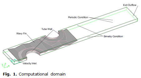
Two regions were artificially extended in the computational domain. At the upstream, a magnitude of twice of height channel was added for considering the inlet effect. The domain was extended six times the tube diameter downstream of the trailing edge of the fin. The extension of computational domain has an important cost in computational time but it is necessary to avoid the presence of reverse flow at the exit. Two regions with symmetrical boundary condition were established at both sides of the domain and two periodic boundary condition were setting at top and bottom of the domain. A velocity inlet condition at inlet section and outflow condition at outlet were established. A boundary condition of constant temperature was used in tube wall and shell conduction through the wall of the cooper tubes was considered. On the fin surface was applied a wall coupled boundary condition to consider the conjugate heat transfer on the surface. The leading and trailing edge of the fin were considered as adiabatic.
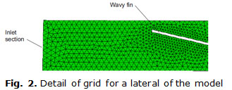
The computational domain was meshed in Gambit software and the grid quality was checked. Several sub domains were used to make easier the grid generation. Two cell were employed in the transversal direction inside the solid fin for considering the heat condition. The air domain was meshed with tetrahedral volumes. The size of volumes was becoming smaller when the fin surface is closer, looking for the higher gradients presented in this area. A total volume number of 2,79 x10⁶ were generated for the finest mesh.
A detail of the initial mesh, before adaption, generated in the lateral part of computational domain is presented in the figure 2. At figure can be observed the reducing size of volumes when they are closer to the fin surface. The picture is just presenting the grid used in the air zone.
The Fluent software was employed for solved the general equations. During the calculation was considered a segregated solver with constant properties. To improve the convergence momentum equations were lightly under relaxed when the higher velocity values were tested. Scale residual were monitored and convergence criteria were set to 10-8 for energy and 10-6 for continuity and velocity components. The mass weighted average temperature at outlet section and the area average pressure in the wake region of the second tube were monitored too. An imperceptible variation of the final values of these magnitudes during 50 iterations was considered as a convergence criteria. The magnitude of the values presented in this work were obtained using a grid adaption register resulting of combining three previous register adaption. Two register were based in velocity and temperature gradients, the other was constructed with the boundary options on the walls and unitary cell distance.
In general the time elapsed for every solution ranged from 6 to 20 hours. The thermal conductivities were set to 202,4 W/mK and 387,6 W/mK for the aluminum fin and cooper tube respectively. A value of 0,25 mm was assigned for the tube wall thickness. The air specific heat at constant pressure was set constant as1006,43 kJ/kgK and density was determined using the ideal gas law.
The discretization scheme used for pressure was the standard while a second order upwind for energy was employed. The second order scheme was selected considering the misalignment between the flow and the grid. This decision is try to avoid the effect of numerical diffusion in misaligned grid. The coupling between pressure and velocity was implemented using the SIMPLE algorithm.
Data Reduction Procedure
The Reynolds number (Re) was determined using the average velocity at channel inlet or front velocity ufront. The characteristic length was the channel height δ. ecuación 1
Where ν is the cinematic viscosity. Heat transferred in a heat exchanger (Q) can be calculated with the change of temperature of the air between the inlet and outlet sections (Tout-Tin), the mass flow through the heat exchanger channel (ma) and knowing the fluid properties. ecuación 2
Where cpa is the specific heat at constant pressure for the air. When a fluid is experimenting a phase change inside tubes is a common practice to consider an elevated value for the film heat transfer coefficient inside the tubes. This assumption is important because a global heat transfer coefficient can be obtained considering only the external film heat transfer coefficient and the conduction inside the tube wall. The temperature of the internal wall of tubes is constant and with the same value than the refrigerant temperature flowing inside the tubes. The heat transferred (Qh) can be calculated using the logarithmic mean temperature difference LMTD (ΔTln) method, knowing the heat transfer area (Af) and the global heat transfer coefficient ![]() by: ecuación 3
by: ecuación 3
The LMTD correction factor, F, was considered unitary because one of the fluids flowing through the heat exchanger keep a constant temperature. The global heat transfer coefficient, will be calculated considering the equality of the heats calculated by equations 2 and 3:
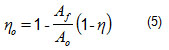
The efficacy η0 of the fin is involved and at the same time, efficacy is a function of the global heat transfer coefficient, then the efficacy can be calculated if the fin efficiency η is known and Af/Ao is the rate of heat transfer area to the base area of the fin, as: ecuación 5
The fin efficiency for the rectangular fin was determined using an approximate method developed by Schmidt for circular fin. The fin efficiency is expressed by: ecuación 6
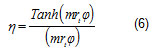
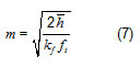
the parameter m was calculated with the thermal conductivity (kf) of the fin and the fin thickness (ft). ecuación 7
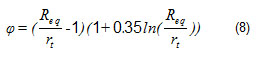
on the other hand, the term φ is obtained with the equivalent tube radio divided by the tube radio (Req/rt). This parameter just depending on the heat exchanger geometry. ecuación 8
then: ecuación 9
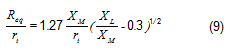
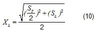
where XM is a half transversal pitch and XL is calculated by the following equation, where ST and SL are the transversal and longitudinal pitch respectively: ecuación 10
The fin efficacy and the global heat transfer coefficient have an implicit formulation therefore an iterative procedure is needed. The condition of equality of the heats Q=Qh (equation 4) must be satisfied. For a fixed geometry there are only a pair of values fin efficacy and global heat transfer coefficients, which satisfy the equality.
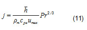
The Colburn factor j could be calculated having the global heat transfer coefficient, the velocity in the minimal cross section of the channel (umax), the heat capacity at constant pressure of the air, the Prandtl number (Pr) and the average air density ρm. ecuación 11
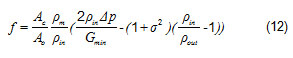
The friction factor f was used for the hydraulic characterization of the heat exchanger model. The friction factor was calculated using the Kay and London definition, where Ac is the minimum flow area, Ao is the total area, Pin and Pout are the air density at the in an out sections respectively. σ is the contraction area ratio, Δp is the pressure drop and Gmin is the mass flux in the minimal flow area: ecuación 12
Validation of the numerical model
The values of the heat transfer coefficient and pressure drop were used to calculate the Colburn factor and the friction factor. These values were represented in the figure 3 and compare to the same parameters obtained by Wang et al (1996). The Colburn factor was calculated using the multiplication of the average heat transfer coefficient by the efficacy of the fin. The uncertainties in the reference were expressed for j and f but only values of global heat transfer coefficient and pressure drop could be obtained with accuracy enough from graphics present in the reference. In the figure 3 can be noted a good match between experimental and numerical result obtained in this work.
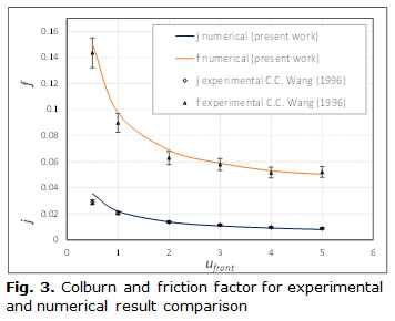
Only for the lower Reynolds number there was an overestimation of the Colburn factor. At lower Reynolds number there was an important divergence between the LMTD and the normal temperature differences. The divergence was disappearing when the exit temperature of the model was augmenting. Normally the LMTD is lust a little lower than the arithmetic mean thermal difference (AMTD). At lowest velocities, there are an important difference between these magnitudes then the last one could better represent the actual mean thermal difference. It is only an author opinion and it wasn't used in this work.
RESULTS AND DISCUSSION
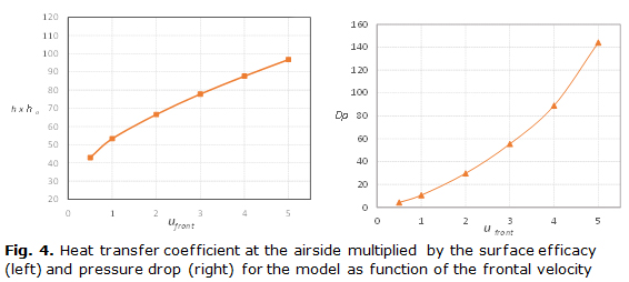
The film heat transfer coefficients at the airside obtained from the numerical simulation are presented in the figure 4 as function of frontal velocity. Values of h for 0,5 m/s of frontal velocity are overestimated as was mentioned above. The surface efficacy values, obtained by the Schmidt method, were always higher than 80 %. The heat transfer performance was found increasing with the frontal velocity, but the enhancement rate diminishes as frontal velocity grows. The pressure drop through the model was investigated too and its behavior is presented as a function of the frontal velocity at figure 4. The pressure drop was increasing with the frontal velocity. Since of an extended computational domain was used, the pressure drop is considering the inlet and exit effects.
The heat transfer performance for the wavy fin is higher when compare to a plate fin with the same dimensions. The enhancement effect is associated with the oscillating movement of the air through the model. This kind of flow pattern produces successive changes in the flow direction. A vector velocity representation on a plane perpendicular to the fin surface and located at border of the computational domain (lateral view) can be observed at figure 5. The pictures is showing the successive changes in the flow direction and the horseshoe vortices created at the stagnation point in front of tube. The picture is presenting only the region from the leading edge up to stagnation point of the second row tube. In this figure 5, only qualitative information is presented.
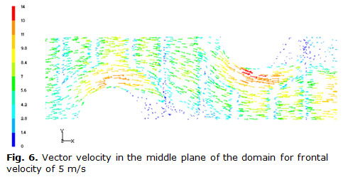
A top view from a middle plane in the center of domain, located at Z = 1mm is presented at figure 6 for 5 m/s. The vectors velocity red colored can distinguish the local acceleration of the fluid where the tube are obstructing the channel. The horseshoes vortex system created at the stagnation point of every tube characterize this region. The effect is more intense at the second row because of the redirection of the flow caused by the first row of tube. Since the fin has a saw tooth geometry the vector velocities are presenting oscillating values (the blue color is associated with the lowest values of velocity). That is because the middle plane has a variable distance from the fin surface. Where the velocity has lower value the fin surface is closer to the plane and vice versa.
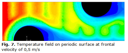
The variable distance from a horizontal plane up to the fin, produces at the same time a characteristic behavior of the temperature. The thermal boundary layer on the fin surface is alternatively close and far from the presented plane at figure 7. The plane is presenting the periodic surface on the top of the computational domain. The blue color corresponding to 286 K and the red with 300 K
The temperature field can be analyzed in a plane at middle of the computational domain and perpendicular to the fin (Y = 6,25 mm) presented at figure 8. The flow inlet direction is from right to left. Can be noted how the fluid with a constant temperature profile is encountering with the solid fin and the temperature difference between them begin to make lower. This lower temperature difference is responsible by the diminishing driving force of the heat transfer from the hot air to the cold fin. This situation is more accentuated when the frontal velocity is lower because a higher residence time of the air inside the channel. Of course, the presence of tubes and the irregularities of the fin has an influence on this thermal difference at local level and, in that way, the heat transferred through the fin is modified.
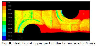
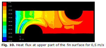
The heat transferred on the fin can be separated in two parts. There is a heat transferred at the upper part of the fin and at the same time there is a heat transferred at the bottom part of the fin. The herringbone structure of the wavy fin has a significant importance on the heat transferred. At figures, 9 and 10 the heat transferred by the upper part of the fin for two different frontal velocities is showed. The heat transferred by the first row of tubes is higher than heat transferred in the second row for the two frontal velocities. A local higher velocities associated with the horseshoes vortex system forming in the stagnation point at surrounding the tubes is responsible for the higher heat transferred in these areas. Developing boundary layer at the leading edge of the fin is another mechanism responsible for highest heat transferred locally.
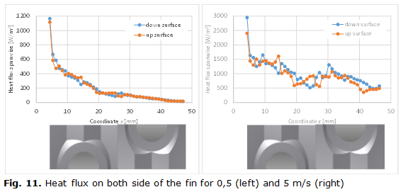
When the heat transferred at the upper part of the fin is compare to the transferred at the bottom part, some differences can be noted. The figure 11 is presenting the heat flux spanwise at upper and bottom part of the fin for two different frontal velocities. At figure 11 can be noted how the maximum value of heat transferred at upper part with the minimum value of the same parameter but in the bottom part are coincident. This behavior is associated with the successive alternate of the flow direction and with the fact that, in some areas, the flow is impinging on the surface. Must be remembered that the velocity profile at inlet section is one-dimensional and the vector velocity direction is coinciding with the X coordinate.
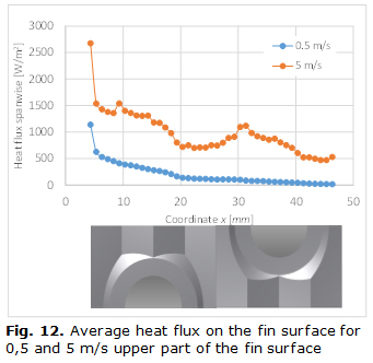
The above mentioned behavior is not observed when the whole heat transferred at the fin is considered (figure 12). The peak on the heat transferred are now just on the stagnation point of every tube at it is observable only for the higher velocity. This is produced by cancellation of minimum and maximum when the average value is considered.
CONCLUSIONS
The characteristic of the flow and heat transferred in a wavy fin was determined as a function of the frontal velocity. A complex fin geometry was created in Inventor and meshed in Gambit. A good quality of the mesh was observed and the result presented here were not mesh dependent. The successive alternating flow direction produced by the herringbone structure of the fin was responsible for the thermal-hydraulic behavior of the fin. The numerical model used was certificated by comparison with published in the literature. The local value of velocity, temperature and heat transferred were analyzed. The flow impinging on the fin surface was found responsible for the difference between the heats transferred at every side of the fin. A periodic condition was employed at bottom and top of the computational domain and it was implemented with a fin located in the middle of it. The implemented model will be useful for analyses some enhancement technique applied on the fin surface.
REFERENCES
1. Wang CC, Chen PY, Jang JY. Heat transfer and friction characteristics of convex louver fin and tube heat exchangers. Experimental Heat Transfer. 1996;(9):61-78. ISSN 1521-0480.
2. Wang CC, Yur TL, Chi JL, et al. Investigation of wavy fin and tube heat exchangers: a contribution to databank. Experimental Heat Transfer. 1999;(12):73-89. ISSN 1521-0480.
3. Fan Jf, Ya Ling H, Wen Quan T. Application of combined enhanced techniques for design of highly efficient air heat transfer surface. Heat and Mass Transfer. 2012;1(33):52-62. ISSN 1432-1181.
4. Islam Akm S, Arafat AB. A numerical investigation on heat transfer and pressure drop performance of typical wavy fin and tube heat exchanger. In: Proceeding of the 7th Jordanian International Mechanical Engineering Conference (JIMEC' 7 ); 2010. p. 27-9.
5. Glazar V, Trp A, Kristian L. Numerical study of heat transfer and analysis of optimal fin pitch in a wavy fin and tube heat exchanger. Heat Transfer Engineering. 2012;2(33):88-96. ISSN 1521-0537.
6. Gong J, Min C, Qi C, et al. Numerical simulation of flow and heat transfer characteristics in wavy fin-and-tube heat exchanger with combined longitudinal vortex generators. International Communications in Heat and Mass Transfer. 2013;43:53-6. ISSN 0735-1933. DOI 10.1016/j.icheatmasstransfer.2013.01.004.
7. Dong J, Su L, Chen Q, et al. Experimental study on thermal-hydraulic performance of a wavy fin-and-flat tube aluminum heat exchanger. Applied Thermal Engineering. 2013;51(1-2):32-9. ISSN 1359-4311. DOI 10.1016/j.applthermaleng.2012.09.018p.
8. Du X, Feng L, Yang Y, et al. Experimental study on heat transfer enhancement of wavy finned flat tube with longitudinal vortex generators. Applied Thermal Engineering. 2013;50(1):55-62. ISSN 1359-4311. DOI 10.1016/j.applthermaleng. 2012.05.024.
9. Lotfi B, Zeng M, Sund B, et al. 3D numerical investigation of flow and heat transfer characteristics in smooth wavy fin and elliptical tube heat exchangers using new type vortex generators. Energy. 2014;73. ISSN 0360-5442. DOI 10.1016/j.energy.2014.06.016.
10. Kale SS, Bhatkar VW, Dange MM. Performance evaluation of plate fin and tube heat exchanger with wavy fins a review. Engineering. 2014;4(9):154-8. ISSN 1947-394X
11. Tao YB, He YL, Huang J, et al. Three dimensional numerical study of wavy fin-and-tube heat exchangers and field synergy principle analysis. International Journal of Heat and Mass Transfer. 2007;50:1163-75. ISSN 0017-9310. DOI 10.1016/j.ijheatmasstransfer.2006.03.019.
12. Huisseune henk T, Christophe J, De jaeger P, et al. Performance enhancement of a louvered fin heat exchanger by using delta winglet vortex generators. International Journal of Heat and Mass Transfer. 2013;56:457-87. ISSN 0017-9310
Recibido: 27 de octubre de 2015.
Aceptado: 27 de diciembre de 2015.
Rubén Borrajo-Pérez. Instituto Superior Politécnico José Antonio Echeverría, Facultad de Ingeniería Mecánica. La Habana, Cuba
Correo electrónico: rborrajo@ceter.cujae.edu.cu

