


 Serviços customizados
 Inglês (pdf)
 Artigo em XML
 Referências do artigo
 Enviar este artigo por email
 Citado por SciELO
  Similares em
SciELO
Similares em
SciELO 
 Permalink
Introduction
We can consider the Mechatronics as an integrative discipline using the technologies of mechanical engineering, electrical engineering/electronics and information technology in order to provide enhanced products, processes and systems [1,2].
As mechatronic systems encompass a wide range of disciplines, thus, the design of mechatronic systems requires a multidisciplinary integrated design. The design methodology can help the engineers from different disciplines to enable their collaboration for increasingly complex tasks. However, neither academia nor industry has yet provided an effective design methodology, which can fully support the engineers to achieve such multidisciplinary integration [3,4]. Besides, in the mechatronic system development process, not only are the geometrical design parameters themselves interdependent, they also depend on the design parameters of the various discipline involved [5-7].
Mechatronic design is a multi-level process relying on both existing and developed mechatronic components. Requirements need to be satisfied at different levels ranging from high-level system requirements to detailed design decisions. When designing mechatronic systems, engineers are combining derived components with custom-made components, a scenario that needs further investigation [8-11].
The paper presents a new approach to integrate the functional requirements analysis from conceptual design of mechatronics products, to aid the designers to overcome the variety of data-related problems and to achieve the integrated multidisciplinary design of mechatronic products.
Reference Model
The current mechatronic product solution space in mechanical engineering, suffers badly from a lack of tools to evaluate engineering criteria through the product design lifecycle [12,13], like the conceptual evaluation of functional requirements. These approaches are not able to capture sufficiently and process the information related to the different scenarios and point of view of a mechatronic product, mainly in the first stage of the product design process. The effect of lack of tools for the product design conceptual evaluation of functional requirements’ formulation results in large budgets being spent on time-consuming system calculation tasks afterwards, in the following steps of the development process.
To meet these challenges, enterprises are today looking for integrating their engineering tools into their enterprise architectures. Enterprise architecture frameworks provide guidelines to separate and document different concerns of an enterprise and its infrastructure into views pertinent for their stakeholders. Examples of such frameworks are DoDAF (Department of Defense Architecture Framework), Treasury Enterprise Architecture Framework, TOGAF (Open Group Architectural Framework), GERAM (Generalized Enterprise Architecture & Methodology) and the Zachman Framework. Shortcomings of these frameworks are that they tend to be documentation heavy or process-heavy and they do not provide operational support [14].
We need collaboration between designers for the mechatronic product design whit the objective of achieving a better management of product from different points of view. The studies about functional requirements management in mechatronic conceptual design are sparse, and mainly dedicated to process requirements description.
In a typical mechatronic product conceptual design process, collaboration between multiple engineers is required to consider different product aspects. We can see from different actors’ points of view, as follow: a design engineer considers the product to function efficiently and reliably; another engineer considers manufacturing rules for the product in large numbers, quickly and cheaply with the lowest possible number of defects; electrical engineers have regards for the electrical components and so on. Each engineer plays a role as a stakeholder generating information from his point of view, which influences the mechatronic conceptual design through his response.
Thus, the consideration of multiple points of views is essential in a mechatronic product conceptual design process, to avoid product design decision mistakes, to shorten design-merging time and to control design quality.To develop a new approach to integrated the functional requirements analysis from conceptual design of mechatronics products, this research work proposes the use of an attached model of the Virtual Service Enterprise and a reference model that allows the enterprises to create a particular model to set-up successful IPPMD (Integrated Product, Process and Manufacturing System Development Processes) [15].
The IPPMD reference model is independent of the enterprise industrial sector, but focuses on specific issues such as market opportunities, technological constraints and declared goals. This model has been tested for different integral product development scenarios [15].
The VSE (Virtual Service Enterprise) model consists of three main elements, see figure 1, a):
The service network in the operation phase has an array of service-products, which they can offer to the customers.
The VSE is formed of selected network members. Together, they can fulfill the specified service-product.
The service-product is divided into different tasks. Each VSE member is responsible for performing a part of these tasks in accordance with its competences and available technical aids and ICT resources.
The VERA (Virtual Enterprise Reference Architecture), see figure 1, a), allows a complete representation of the product lifecycle stages, from a methodological point of view and also permits the analysis of the instantiation for a particular case of an enterprise [16]. At the same time, it enables a cross-organizational and cross-industry sharing of experiences gained. The present approach introduces a reference model coupled with VERA.
We define the reference model developed as the complete representation of activities of the product lifecycle. The proposed reference model is described through three basic components, see figure 1, b): (i) the ‘stages’ of the product development; (ii) the ‘views’ involved in the process; and (iii) the ‘entities’ of the product development. The properties of this reference model are:
Reusability-Configurability: the ability to be configured in a particular model to get a specific goal in the product lifecycle focusing on specific issues of the enterprise like: market, knowledge and technology.
Integral: due to its structure, the model is able to adopt new methods and tools from different disciplines and integrate them to allow a further development of particular models for different industries.
Robustness: based-on a proven library of methods and tools to ensure the information flow among the product development stages and avoid the lack of collaboration between design engineers and manufacturing engineers.
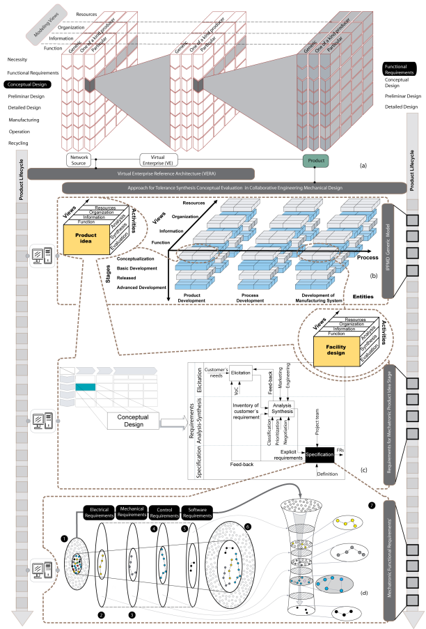
Based-on the reference model proposed we develop a particular model to integrate the functional requirements analysis from conceptual design of mechatronics products design, see figure 1, c & d). We present the details in the following sections.
The mechatronic product model to integrate the functional requirements analysis
We propose the general characteristics of a particular model to integrate the functional requirements analysis from conceptual design of mechatronics products design to fill the gaps that we found in the literature review. The major attribute of the approach proposed is its integration to the IPPMD reference model and the VERA. The figure 1 shows how the approach begins from the conceptual stage of a mechatronic product, in the context of a VSE. The reach of the proposed approach is centered in concrete stages of the mechatronic product design process: definition of the product functional requirements and conceptual design, guided to the product conceptual evaluation of alternatives.
To represent the specification of the requirements for a mechatronic product, we propose a set of four layers to apply to the functional requirements. Each layer established constitutes a formalization of the knowledge related with each point of view for a mechatronic product (electrical, control, mechanical and software). These layers are filters that classify and group the functional requirements. The process, see figure 1, d), has as entry elements, the mechatronic product functional requirements (1). The first layer it is related to the electrical functional requirements (2), the second layer (3) filter the mechanical functional requirements, the third later (4) group the control functional requirements and the last layer (5) filter the control functional requirements.
The following section shows a study case that serve as illustration of the validity of the developed approach.
Conceptual mechatronic product model study case
We show in this study how to implement the analysis and definition of functional requirements of a mechatronic product. In this case, we will analyze the conceptual design of a multi-functional and reconfigurable CNC (Computerized Numerical Control) micro machine tool for Maker Space. The aim of this micro machine tool is to satisfy the need to have in the educational field a micro CNC machine tool, which facilitates to students to reconfigure the function of the micro machine from the definition of the technological path of the manufacturing process (It has the facility to be reconfigured in eight possible micro machine tools).
Once defined which social and technological megatrends are related to the idea or product to be developed, three tools are used for this case study that facilitate the beginning of the structuring of ideas: the tasks to be performed: Jobs To Be Done, Expected Expectations and Value Proposition (not covered in this article).
The value proposal visualizes and structures in a first instance, the preliminary idea to develop. In the Design Phase, the functionalities and attributes of the product are determined, a match is made between the requirements of the client and the engineering requirements, the preliminary virtual prototypes are realized and a storyboard is projected. All these aspects are transforming the requirements of the product from an abstract phase to a more concrete one. We will only focus on the functional requirements and their relationship with functional structuring.
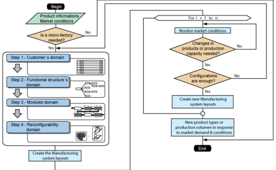
We can consider the information in the design process is largely product oriented. We can also take into account that, the process through which the final design and its different stages are complete is fundamentally implicit in the same design process. In order to capture and represent it, several investigations have been carried out that have originated new methods.In practice, little research has been done on aspects related to the capture and description of decision making in the design process. Many of the approaches in this area prescribe only the format in which the information is to be captured, but not how to proceed to analyze it in detail and to structure it. Based-on previous analysis, the figure 2 show a framework of micro-factories manufacturing system layouts based on RµM2T, which can be implemented in the advanced development production system, on-site manufacturing system or mobile manufacturing systemand which is taken as reference for the case study.
The framework consists of four stages. Step A begins the process of searching for the information needed for decision-making, regarding whether or not to develop a micro-factory. If the decision is to build a micro-factory, it goes to step B. At this stage are created different possible configurations of the micro machine tools that conform the micro-factory, according to the established requirements. Stage C defines the different layouts that could form the micro factory according to the identified needs. Finally, stage D makes the process of monitoring needs in order to reconfigure the micro-factory in terms of the new needs identified [17].
Once the decision is made to manufacture a micro factory, each of the micro machines that will make it must be designed. We develop a methodology for the design of Reconfigurable Micro Machine Tools (RµM2T), figure 3.
The first step of the methodology allows accomplishing the customer’s domain. This domain has the purpose of collecting the appropriate information from customers, related to the purpose and characteristics of the RµM2T and the micro-parts to be machined, based-on a more detailed level of information to facilitate the search for solutions. To explore this domain, the methodology proposes a first activity, associated to the identification of the operational needs of the micro-machine tools and the micro-parts.
The operational needs identification must be catalogued in: accuracy of the micro-machines and the micro-parts to be machined, structural characteristic of the micro-machines, vibration characteristics, preliminary kinematic analysis, thermal performance, and so forth (2), figure 3.An important element in this phase is the characterization of the family of parts to be produced, an essential element in defining the reconfigurability of the RμM2Ts, based on knowing the typical technological operations that must be performed. We can identify and evaluate these two aspects based on the information that the client has, and which is evidence using specialized tools such as:DSM (Design Structure Matrix) [18], Kano [19] and QFD(Quality Function Deployment) [20].
The second step of the methodology, see figure 3, permits to carry out the functional structure’s domain. This domain is significant for the methodology, because it states the necessary functional base, that we will use in the following steps to find out the reconfigurability of the RµM2T.
This domain has the purpose of transforming the customer needs (3) analyzed in the previous step, in a functional structure of the RµM2T. The main elements that influence in the determination of the functional structure of the RµM2T (7) are the technological processes defined in the previous step of the methodology. This domain includes two key activities. The first one, is related to the identification of the operating modes of the RµM2T (5). Each operating mode characterizes the functionalities of the RµM2T, in response to the range of the technological processes defined.For each mode of operation, we have to identify the global function and set up the functional decomposition. Once concluded this process, we have a set of functional structures (4), in response to each mode of operation (6) (Figure 3).
We can analyze the functional requirements of a mechatronic product from three points of views: the elicitation of the functional requirements for the Stakeholders; the analysis of the functional requirements for the Stakeholders; and the requirements specification (3). In this paper, we focus on the last point of view. The requirement specification (3) is one the input for the functional structure (4) definition in a mechatronic product, figure 3.
In this way, we must execute adequately the requirement specification (3) by several methods and tools, for example, applying the Kano method, applying the DSM approach and applying the QFD method. When anyone of these tools is applied, we have relevant information that we are going to be using in the definition of the functional structure of a mechatronic product.
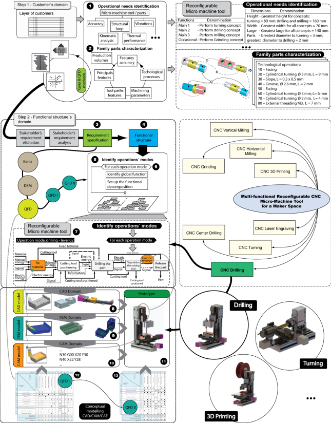
Fig. 3 Customer’s and functional structure’s domain steps of the methodology and their relation with the CAD/CAM/CAE tools
The output of every method (Kano, DSM and QFD) makes easy the decomposition of the functional requirements. This decomposition allows forming the different requirements for every point of views related to the mechatronic products, i.e. electrical, control, mechanical and software.
We embed the information related to the functional requirements in the CAD (Computer Aided Design) model (8), when the designer transforms the functional structure in a conceptual CAD model. Then, we use the CAD model to support the FEM (Finite Element Method) (9), with the end purpose to carry out a numerical simulation about the behavior of the conceptual solution of a mechatronic product. After that, we submit the approved solution to the CAM (Computer Aided Manufacturing) module (10), where we are going to simulate each part in a CAM environment, figure 3.
Finally, the virtual prototype (11) is the synthesis of the above relationships, where the functional requirements are the thread that contains the relevant information based-on the customer necessities. Otherwise, the QFD output information (12 and 13) is transformed in parts and modules of the mechatronic product, figure 3.

The figure 4 shows the case study of a reconfigurable micro machine tool, in the configuration of vertical micro drill. We can see the process of transforming information preferably of semantic type (1 and 2) with a high degree of uncertainty, contained in the domain of the requirements, to a functional physical prototype (7). We can observe the classical structuring of the prescriptive design, where an iterative process occurs from the decision making to the selection of the concept (3). This figure graphically represents the way in which the requirements are evolving and how they are gradually being synthesized until they we see it in the selected concept. In this analysis, we can use the CAD/CAE (Computer Aided Design/Computer Aided Engineering) tools to validate the fundamental parameters of the virtual prototype. This prototype possesses, intrinsically, the functional requirements of a mechatronic product (requirements related to the domains: electrical, control, software and mechanic).
The basic design stage (4) facilitates, from the selected concept, to define the preliminary forms of the design, the selection of the materials of the parts, the basic calculations of structural type, strength of materials, and so on. In this way, we translate the functional requirements into engineering specifications with a more concrete character, to finally obtain the definitive typology of the product (5).
Finally, the conclusive stage of the design process (6) compiles all the information necessary for the manufacture and assembly of the physical prototype (7), which must meet the expectations and functional requirements of a mechatronic product, as analyzed previously.
Conclusions
The approach proves that the analysis of the functional requirements of mechatronic products could be based-on the IPPMD (Integrated Product, Process and Manufacturing System Development Reference Model) to improve the mechatronic products design. The approach enables the top down instantiation process, in order that the designer’s activities related to mechatronic will be executed.

