


 Servicios personalizados
 Español (pdf)
 Articulo en XML
 Referencias del artículo
 Enviar articulo por email
 Citado por SciELO
  Similares en
SciELO
Similares en
SciELO 
 Permalink
Introduction
The sun is the most important energy source to the earth, its radiation reaches every part of the world and the total irradiance on the earth´s surface is enough to satisfy the energy needs of the whole humankind [1]. Solar air heaters (SAH) allow to employ renewable energy during the heating and drying process. Expensive solar air collectors can be found in [2, 3], contrasting with those with a cheaper design. For instance, plastic was employed for Abdullah et al, [4] to build three solar air heaters arrangements. The mass flow rate in forced regime was varied and its influence analyzed. Three different shapes of transparent cover were essayed: circular, plane and triangular, each one of them with a semicircular region attached to the bottom. The model thermal efficiency was used as a comparison tool. The thermal efficiency of the circular shape presented the best value with an 80 %. The triangular configuration depicted the worst one.
Continuing this trend, a double-pass solar air heater was experimentally researched in Raj et al, [5]. The SAH had two asymmetric channels in a forced convection condition. The data were analyzed using a neural network system. The energy and exergetic efficiencies were calculated. During the analysis, the influence of several parameters on the thermohydraulic performance was determined. The solar radiation and ambient temperature were the most relevant parameters. The higher thermal efficiency calculated was equal to 41 %. The channels depth influence was obtained and the temperature was found higher in the lower channel than in the upper channel. A deeper channel leads to a lower temperature, as a consequence of a higher mass flow rate. A complex flow pattern inside a solar air heater was imposed by Heydari and Mesgarpour [6]. Experimental and numerical approaches were employed to investigated an innovative solar air collector with a helical flow path. The air channel cross section had a triangular shape to guarantee a larger residence time to the flow. Higher thermal efficiencies were calculated for the condition with the higher mass flow rate. Thermal efficiency values were found ranging from 55.4 % to 41.84 % as a function of the mass flow rate. Additionally, the impact on the SAH performance due to the heated fluid was numerically simulated. As a result, when compare with carbon dioxide or air, the nitrogen was identified as the best alternative.
An investigation concerned to several arrangements of SAH with multiple channels was carried on by Phu and Luam [7]. They applied the thermodynamics analysis to the results and performed a multi-objective optimization. Four models having two-pass or three-pass were implemented and a single pass model was used as a comparison baseline. The effective efficiency was found increasing with the pass number. The multi-objective optimization shown the triple channel flow is the best option at low mass flow rate. Although, at high mass flow rate the exergetic efficiency was the worst. The effective efficiency decreases when the channel length is higher but, an opposite trend is observed for the exergetic efficiency. Experimental approach as the employed by Singh et al, [8] are been complemented with numerical simulations to demonstrate the usefulness of that mathematical tool [9].
In general, there are a lot of works dealing with solar air collectors. A recent search in Science Direct produced 36000 occurrences related to solar air heater although just journals belonging to the last ten years were included. However, a high number of review papers envisioning to collect and synthetize the information are available in the published literature at present [10]. Special topics related to the internal matrix of the SAH has been considered in [11], where mesh wire and porous material were essayed. Probably, the heat transfer enhancement on the absorber plate is among the most investigated topics in the field of SAH, as can be appreciated in [12, 13]. This tendency is also stablished for solar water heater as was reflected in Murugan et al, [14]. Nevertheless, there are simpler solutions to increase the SAH’s performance [15]. Parametric studies are an important tendency in SAH research [16] because every involved magnitude impact the thermohydraulic performance in a very particular way. In search of simplicity, this work is intended to determine numerically what must be the best position for the absorber plate if the air channel is splitted in two separate channels and a turbulent flow regime is imposed.
Materials and Methods
The SAH investigated is a flat solar collector having a simple design. It comprised of a glass cover, a straight air channel -splitted in two channels for some configurations-, an absorber plate, and an insulated bottom. Generally, all components are contained in a metal case with its edges thermally insulated. The air is forced into the inlet channel and it is exiting through the outlet section. The incident solar radiation on the absorber plate is fundamentally determined by the geographic location, time, climate conditions, and the collector tilt angle. The solar radiation passing through the glass cover and heating the plate, is slightly lower than the incident radiation, because a small quantity is absorbed by the glass. The air circulating inside the channel collector increase its temperature because there is heat transferred from the absorber plate and from the glass internal side. Heat losses are occurring from the glass cover and from the bottom, due to convective and radiative heat transfer. To simulate the solar performance, a computational domain representing the physical domain must be generated. The figure 1 presents the computational domain constructed to emulate the air solar collector performance. The analyzed solar collector had two meters’ length, and the air channel height is about eighty millimeters. To reduce the domain size and the computation time, only a section of the real collector is analyzed. With such objective in mind a bilateral symmetric condition is applied.

The boundary conditions are indicated in the figure 1. Both lateral surfaces limiting the domain were considered symmetric, equation (1):
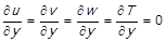 (1)
(1)
At the inlet of the domain one-dimensional profiles for velocity and temperature were imposed. The inlet temperature is 300 K and the inlet velocity was varied from 0.5 to 4 m/s. Then, at the inlet T = T in and u = u in .
All solid surfaces were treated as impermeable walls with no slip condition. A conjugate heat transfer problem is resolved on the walls, where a contact between fluid and solid exist. At the outlet, a nil gage pressure is imposed, where the velocity and temperature profile are not more a function of the x coordinate, equation (2):
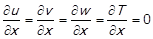 (2)
(2)
The computational domain was extended at the inlet and outlet. These two additional channels -not presented in their real magnitudes on figure 1 are in agreement with the ASHRAE standard 93 -77 apud Manjunath et al, [16], which fix their lengths in 5 (WH)0.5 and 2.5 (WH)0.5 for the inlet and the outlet extensions respectively. All the channel extension boundaries were also considered symmetric. The extensions allow to include the inlet and outlet pressure effects in the numerical model. Additionally, the final extension avoids reverse flows at the outlet section. The solar radiation was simulated as internal generation sources divided into the absorber plate and the glass. The assigned values in W/m3 assure a total energy source of 400 W to the studied model section.
The numerical simulation was carried out in steady regime and inside the turbulent flow regime, with constant physical properties. The temperature and velocity fields were treated as uncoupled. No buoyancy effects were regarded. A second order interpolation was implemented for the momentum and energy equations. However, for the parameters k and epsilon, associated to the turbulence model k-e RNG, a first order interpolation was used. The selected turbulence model is among the most employed for SAH researches [10] in forced regime of flow. The properties of the air and materials involved in the numerical model, are included in table 1 in agreement with Moraton et al, [15].
Table 1 Material properties. Source: [15]
| Material | Thermal conductivity (W/m K) | Density (kg/m3) | Specific heat at constant pressure (J/kg K) |
|---|---|---|---|
| Air | 0.0242 | 1.225 | 1006.43 |
| Steel | 16.3000 | 8030.000 | 502.50 |
| Glass | 1.1500 | 2200.000 | 830.00 |
| Insulation | 0.1000 | 20.000 | 830.00 |
Data reduction
The heat gained by the air in the solar collector, Q, is determined as a function of the outlet and the inlet temperatures T
out
, T
in
respectively. In the equation (3),  represents the mass flow rate calculated by the continuity equation, m = ρacinAin. Where ρa is the air density at the inlet, cin and Ain are the inlet velocity and the inlet cross section area respectively. cp is the air specific heat at constant pressure.
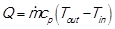 (3)
(3)
The heat transfer coefficient on the absorber plate is calculated in the equation (4) with the air mean temperature inside the collector  and the average temperature of the absorber plate
  .
.
 (4)
(4)
Where A is the heat transfer area.
The effective thermal efficiency in equation (5) is obtained considering the heat gained by the air, the solar radiation I
s
, and a coefficient C
0
to stablish an equivalence between heat and power. The selected coefficient value is 0.18 and the pumping power, W
p
, is determined by the equation (6), where Δp is the air pressure drop through the collector and  is the air density obtained with the air mean temperature.
 (5)
(5)
 (6)
(6)
The exergetic efficiency of the air solar collector is calculated with the exergy change experimented by the air crossing the collector, ΔEx. In the equation (7), T 0 is 298 K, R a is the air constant and p out and p in are the mass averaged of the air absolute pressure at the outlet and inlet sections respectively. The variations in potential and kinetics energy were disregarded.
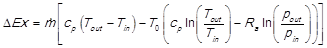 (7)
(7)
Having the solar radiation exergy, Ex sol , determined by the Jeter’s model (12), the exergetic efficiency is, equation (8):
 (8)
(8)
The convective heat transfer coefficient h per to define the heat losses is calculated in relation to the wind velocity c w around the collector case. equation (9)
 (9)
(9)
The Reynolds number employed herein is based in the inlet velocity, and two times the channel height at the inlet section, as it is usually does in rectangular channels. equation (10).
 (10)
(10)
Finally, in the collector glass cover there are also radiation losses, determined considering an external radiation temperature or T sky equal to 280 K.
The SAH models having dual channels and a flat absorber plate -which are considered herein- are presented on the left at figure 2. A two numbers code was used to name each model. The first number is the dimension in millimeters of the lower channel, and the second number is the dimension in millimeters belonging to the upper channel. Then, for instance, the model 30-50, is a model with a lower channel of 30 mm height and an upper channel of 50 mm height. The absorber plate is always splitting both channels. There are two models with only one channel. They are the model 00-80 with the plate on the bottom, next to the insulation, and the model 80-00 with the plate on top, instead of the glass.
On the right at figure 2 are shown the front, plant and side views of the solar air collector. The represented dimensions are corresponding with the model named 40-40, with both channels having the same height. The sizes of the glass, insulation, and plate, are the same for each model. The solar collector length is also the same for all models.
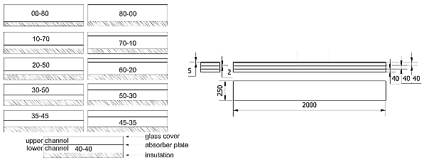 Source: authors
Fig. 2 On the left, the configurations simulated. On the right, the main sizes for the model with configuration 40-40.
Validation and grid convergence study
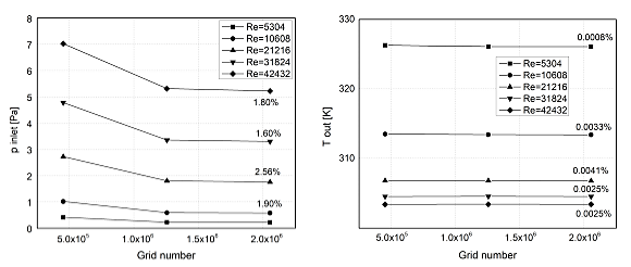
The element type employed in the meshing process were hexagons, in correspondence with the orthogonal shape of the domain. The mesh generation allows the elements size be reduced when they are closing to the walls. The grid independence study was carried out for the model 40-40. Three structured meshes with different densities were created. The model was numerically simulated employing the three meshes for each one Reynolds numbers. The results in outlet temperature and inlet pressure extracted from the simulations were plotted using the grid number as the abscissa axis. As can be observed on figure 3, there is not practically variation between the results obtained by means of the two denser meshes. Above the markers, and only for the densest mesh, are indicated the variation for each magnitude determined with the values corresponding to the two denser meshes. The highest difference was equal to 2.56 % for the inlet pressure at Reynolds number equal to 21216. Considering these results was selected, as definitive, the mesh with the medium density (1.25 x 10⁶ elements), and a similar density value was employed for all models.
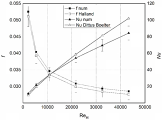
A comparison study was carried out to validate the numerical model herein employed. The model labeled 70-10 was used as a reference for the analysis. The results of the Nusselt number and friction factor for the model were compared to the similar magnitudes, but determined using analytic equations. The numerical results for the friction factor were compared with the Halland equation results for the explicit friction factor in turbulent flow regime [17]. The Numerical results of the Nusselt number were compared to the Nusselt number determined by the Dittus-Boelter equation [18]. Both comparisons were represented on figure 4. Note the error bars sizing ± 10 % added to the analytical results. As can be observed, just for the higher Reynolds number the numerical results are outside the range cover by the error bars, and the model is under estimating the results obtained from Dittus-Boelter equation. In concordance with this validation study, the numerical model herein described is precise enough to reproduce the SAH behavior. The Nusselt number and the friction factor were determined as usually in rectangular channels. The non-dimensional magnitudes are based in the channel hydraulic diameter calculated as twice the channel height.
Results and Discussion
The figure 5 depicts the variation in the outlet temperature and the pressure inlet as a function of the channel height for all the configurations essayed in this research. In the x coordinate axis, the different models are presented. Each curve is for a different inlet velocity. The graphic on the right show a maximum in pressure losses when both channels have the same height (40-40). The pressure drop diminishes at both sides of its maximum value when the channels height is varied. The minimum drop pressure was obtained for the 0-80 and 80-0 configurations, because, there is only one channel in the collector for both configurations. Then is a fact that the hydraulic performance of the dual channel solar collector is improved when a higher difference exists between the channels height and it is worsening when the plate is located next to the collector center.
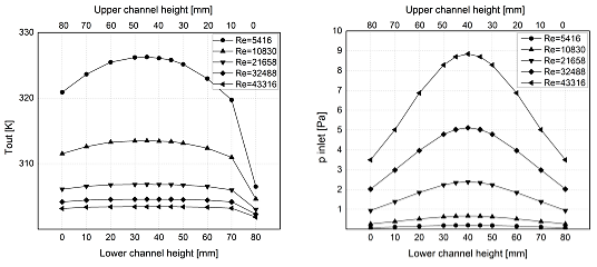
The outlet temperature decreases when the inlet velocity increases and the Reynolds number is higher. That result is due to a higher mass flow rate for a similar solar radiation. The lower outlet temperature is obtained when there is only one channel (80-00) and the absorber plate is located on the channel top. Under such circumstances, massive heat losses are present in the solar collector. The solar radiation directly received by the plate, and the lack of a mass flow on their upper side, produce a higher plate temperature and, as a consequence, the heat losses are substantial. When the plate is located at the channel bottom (00-80), the situation is quite different, because the insulation in the collector bottom limit the heat losses through the wall. The resting configurations present a balance between the heat losses from the glass cover and those from the bottom. The higher outlet temperature is observed for the configuration with a lower channel of 30 mm and an upper channel equal to 50 mm (30-50). For an inlet velocity equal to 0.5 m/s it is perfectly noted, but the same is happening for all the inlet velocities range.
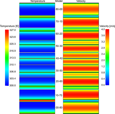
The relation between temperature and flow is much better explained if the temperature and velocity contours on a plane perpendicular to the flow, situated at the channel outlet (x = 250 H), are represented. As can be noted in the figure 6, there is a correspondence between the profiles on the left column with those on the right column. When the lower channel is growing its average velocity in the cross section is increased and its temperature decrease. Meanwhile, the opposite happens when the upper channel height is diminishing and a lower average velocity is noted, then the air mean temperature in the cross section is increased.
 Source: authors
Fig. 6 Temperature and velocity contours for every model. On the left the static temperature contours; on the right the velocity contours. Re = 31824.
The heat losses from the glass cover and bottom of the solar collector are represented in the figure 7. Graphic on the right is for the heat losses from the bottom, meanwhile the graphic on the left is reserved for the heat losses from the glass cover. As can be observed, there is an opposite trend for these two magnitudes, although they are quantitatively different. In general, the heat losses from the glass cover are higher. Should be noted that the thermal boundary condition of this external wall is mixed. Then, radiation and convection losses are simultaneous.

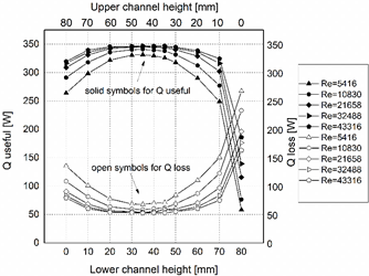
If all the heat losses are gathered and presented in the same graph, is easier to observe the lack of balance existing in between the heat losses. The figure 8 presents, at the same time, the total heat losses from both surfaces and the heat gained by the air through the collector. The contrasting performance in both magnitudes shows how the heat losses are the most important factor influencing the SAH effective thermal efficiency.
Energy and exergetic efficiencies are depicted in figure 9. The energy efficiency increase when the mass flow rate is higher, because a lower outlet temperature reduces the average temperature along the collector impacting directly on the heat losses reduction. From other point of view, the higher values of energy efficiencies are concentrated around the configurations with the absorber plate near to the solar collector center. Actually, as mentioned before, are the heat losses from each surface which decide on this.
If the absorber plate is moved from the bottom toward the channel center, the heat losses from the collector bottom are decreasing, and at the same time, those from the collector cover are increasing. A higher channel height produces a lower average temperature inside the air volume and a lower temperature of the surfaces limiting the channel. Contrarily, a lower channel height, with a lower mass flow rate, contains a fluid with a higher average temperature and higher temperatures on the surfaces in contact with the fluid. This phenomenon moves the point of maximum effective thermal efficiency to a place not located in the channel center. Additionally, a maximum pressure drop exists when the absorber plate is centered in the middle of the channel, contributing slightly to the outcomes obtained for the effective thermal efficiency.
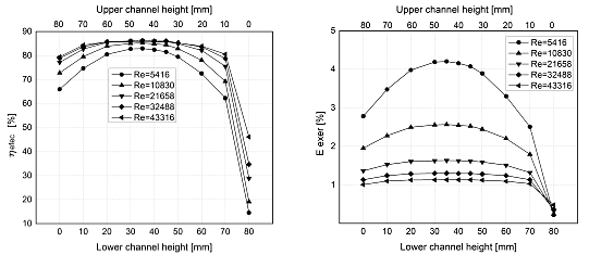
Similar result is found when the exergetic efficiency is considered, but a better resolution is noted. The exergy, based in the second law of thermodynamics, is probably one of the best tools employed to compare heat transfer surfaces (14). The graph on the right in figure 9 show a slightly asymmetric umbrella shape for the exergetic efficiency versus the channel height. The exergetic and effective efficiency are quite low for the configuration with the absorber plate on top and a maximum presented when the lower channel has 30 mm and the upper channel has 50 mm.
Conclusions
A higher pressure drop is produced when the channel height values are closer to each other. A minimum pressure drop was obtained when there is only one channel in the solar collector.
The air outlet temperature was found diminishing with the increase of the Reynolds number because a higher mass flow rate.
The heat losses from the glass cover increase when the absorber plate is closing to the glass cover. In a same way, the heat losses from the bottom increase when the plate is closing to the thermal insulation. However, the heat losses from the cover are higher.
The effective thermal efficiency and the exergetic efficiency are quite affected by the heat losses.
The best SAH performance is determined when the absorber plate is displaced from the channel center, and the upper channel is higher than the lower one.
The collector having only one channel and the plate in the collector top produce significant heat losses and has very low efficiencies.

