


 Serviços customizados
 texto em
  Inglês (pdf)
 Artigo em XML
 Referências do artigo
 Enviar este artigo por email
 Citado por SciELO
  Similares em
SciELO
Similares em
SciELO 
 Permalink
INTRODUCTION
Sugarcane (Saccharum officinarum), is grown in tropical and subtropical regions, significantly increasing exports between 2000 and 2011, mainly in Brazil, which went from exporting 6.5 million tons in 2000 to 25.5 million tons in 2011 , being the largest world exporter of sugar, followed by Mexico, Guatemala and Colombia. In 2000, Cuba was the second largest exporter of sugar in the region, registering 3 500 000 t, falling in 2011 to 648 000 t according to FAO (2014). In recent years, Cuba showed a significant decreasing in sugar production, between other factors, due to low agricultural yields, for which it has been considered necessary to make changes in current agricultural practices (Herrera et al., 2003; Leyva et al., 2007; Betancourt et al., 2008). Among them, the change from the traditional sowing framework to the double row (Romer et al., 2009; Gómez et al., 2011; Ullah et al., 2016; Guru et al., 2017). At the same time, equipment are developed which are adapted to these new planting systems, including those of soil preparation for planting.
Cruz et al. (2018) state that, currently, the technologies used for soil preparation are conventional technology and conservationist. The latter is mainly based on localized preparation of soil, carried out exclusively in the zone of seedling root growth. It is a viable alternative, from the point of view of both, soil conservation and economy of energy resources devoted to the preparation of large areas of land.
The national project Increase in the effectiveness of mechanized processes in the production of sugarcane in the Base Business Unit "Héctor Molina Riaño", belongs to the program Development of the Sugar Agroindustry, run by the Agricultural Mechanization Center (CEMA). As part of this project, it is performed the task Development and evaluation of an implement of localized soil preparation. During the design process of this equipment, it is necessary to carry out certain analyses related to suction and stability, for which an analytical method and software have been developed to avoid the use of cumbersome traditional graphical methods, based on the elaboration of polygons of force and rays that make it difficult the evaluation of multiple variants. In the present work, the developed method and software is presented, through its application in a case study of the aggregate formed by a rubber wheel tractor YTO-1604 and a tillage implement with four staggered shanks. It is aimed at localized soil preparation for sugarcane sowing in double row furrows.
METHODS
Theoretical-Methodological Foundation
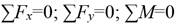
To develop the analytical method of calculation and the corresponding software, the mechanical-mathematical modeling of interaction of the aggregate with the soil was considered firstly, applying the laws of mechanics to the tractor-implement-soil system. Figure 1 shows an isometric view of the tillage implement object of study, where the staggering of four shanks with “V”- shaped blades that work at different depth can be seen, following the principle of the mechanical brush (Albóniga, 2011, 2015; Domínguez et al., 2014).
FIGURE 1 Isometric representation of the tillage implement having four staggered shanks object of study.
The stability conditions are evaluated by determining the loads that act on the wheels of the tractor, both rear and front. In this case, an analysis is made corresponding to a tractor with traction on the rear wheels. It is necessary to clarify that the analysis carried out corresponds to the longitudinal-vertical plane (x-y).
Figure 2 shows the system of forces acting on the aggregate formed by an YTO-1604 tractor with rubber wheels with traction on the rear wheels and the tillage implement having four staggered shanks with “V”- shaped blades.
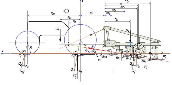
For the achievement of a good "grip" or adhesion of the rear wheels, which enables the transmission of the power demanded in its interaction with the ground, a certain normal reaction force (Nt) in the rear wheel or motor is required (Figure 2) .(If this force does not reach a sufficient value, then wheel slippage may occur and the horizontal component (Pt) of the pulling force required for the work of the implement added to the tractor may not be transmitted. In this case, the work of the aggregate is considered unstable.
Of course, other parameters influence the ability of the driving wheel to transmit the power required through the soil. Among them, there is soil adherence and its state of compaction and humidity, as well as the design of the tires.
On the other hand, in relation to the front wheels, in order to guarantee a good steering of the tractor, an adequate load (Nd) is required on those wheels. It should not be excessive, but neither insufficient, since, in this case, it would be difficult to control the direction of the tractor and in the extreme case, lifting the front wheels. A stable work of the aggregate is complemented with an adequate "suction" of the implement that guarantees the natural penetration of the working implement on the ground with the suspension system working in a floating position. The model presented is implemented in such a way as to facilitate the evaluation of the influence of different parameters on the suction characteristics and stability of the system. Among the parameters that are taken as input variables, are the position of the support wheel, the angle of the wedges that make up the tillage implement of staggered shanks and the position of the instantaneous center of rotation of the tractor suspension system (point π in Figure 2). They, at the same time, constitute elements of design or regulation of the equipment. The forces and coordinates that appear in Figure 2 are the following:
P |
- Force of draft required for the movement of the aggregate; |
β p |
- angle that forms with the horizontal the resultant P of the tensile strength of the tillage implement; |
Pt |
- Horizontal component of the draft force; |
Rx i and Ry i |
- components of the resistance force that acts on each tillage unit; |
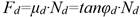
Rxy |
- result of the resistance forces of the soil to the action of the tillage unit; |
Qa, Qt and Qd |
-reactions of the ground on the support wheel of the implement, the rear wheel and the front wheel of the tractor, respectively; |
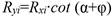
Fa, Ft and Fd |
-horizontal components of the reactions (friction by rolling) Qi; |
Na, Nt and Nd |
-normal components of the Qi reactions; |
φa, φt and φd |
-rolling resistance angles of the implement support wheel, the rear wheel of the tractor and the front wheel of the tractor, respectively; |
Ga and Gt |
- weights of the implement and of the tractor, respectively; |
ra, rt and rd |
-radiuses of the implement support wheel, the rear wheel of the tractor and the front wheel of the tractor, respectively; |
xr i ; yr i |
- coordinates corresponding to the points of application of the forces that act on the multiple bodies that make up the implement; |
xπ; yπ |
- coordinates of the instantaneous center of rotation of the suspension mechanism; |
x |
- horizontal coordinate of the central position of the tillage implement support wheel; |
x ga |
- horizontal coordinate of the center of gravity of the tillage implement; |
x t ; x dt ; x gt |
- coordinates of different characteristic points of the tractor. |
To be able to carry out a stability analysis of the aggregate, it is necessary to determine the values of the vertical reactions that act on the wheels of the tractor. To do this, a quasi-static analysis is carried out, considering that the aggregate moves at a constant speed, which allows applying the equations of static equilibrium of the forces and moments in the x-y plane, that is:
For the analysis, it is assumed that a study of the implement has been carried out, where the suction conditions have been guaranteed. Therefore, the resultant of the forces Rxy, Qa and Ga pass through the instantaneous center of rotation (point π) of the suspension system and the resultant of the forces Ga and Rxy, cause a moment in the direction of deepening of the tillage unit (clockwise in Figure 2). It is also based on the knowledge of the magnitudes, directions and application points of these forces. The geometrical characteristics of the tractor and its weight and position of the center of gravity are also known.
The unknown object of determination for the analysis are the reactions in the front wheels (Qd), in the rear wheels (Qt) and in the support wheels (Qa). It is also necessary to check the condition of penetration or suction of the implement.
As a starting point, it is necessary to determine the loads on the tillage units, which can be calculated knowing the specific resistance of that type of tillage units. In the case of the tillage units of staggered shanks, they are composed of wedges with “V”- shaped blades. Wedges with “V”- shaped blades have been studied by Albóniga (2015), with data on the specific resistance of this type of tillage unit in Ferrallitic-red type soils. Hence, if this indicator and the transversal area of soil that removes each body are known, it is feasible to determine the force of draft corresponding to each tillage unit, by means of the expression:
 (1)
(1)
where:
Rxi |
- Horizontal component of the force of draft corresponding to the Ith tillage unit, N |
Ke |
- Specific resistance coefficient, N/m2 |
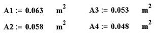
Ai |
- Cross section of the soil section corresponding to the Ith tillage unit, m2 |
The areas Ai are determined on the basis of the geometry of the implements (Figure 3a).
The vertical component and the resultant of the pulling force in each tillage unit are determined by the trigonometric expressions:
 (2)
(2)
 (3)
(3)
The rolling friction forces on the support (F), front (Fd) and rear wheels of the tractor (Ft) are related to the normal reactions through the respective rolling resistance coefficients (µ a , µ d and µ t ):
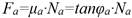 (4)
(4)(4)
 (5)
(5)
 (6)
(6)
The coefficient of rolling resistance depends on the type and characteristics of the soil, the dimensions and characteristics of the wheels and their inflation pressure, among other factors. In Figure 4, a nomogram is provided that makes it possible to determine with sufficient approximation this coefficient for the case of rubber wheels (Sablikov, 1978).
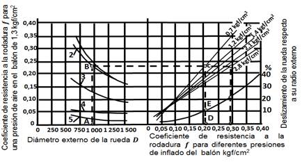
FIGURE 4 Coefficient of resistance to rolling and sliding of pneumatic wheels: 1-loose sandy soil; 2-carved semiarcillous soil; 3-sowing soil; 4-harvested soil; 5-asphalt. Source: (Sablikov, 1978).
The vertical reaction in the support wheels is determined by taking moments in relation to the instantaneous center of rotation (π) of the suspension mechanism (Figure 2):
 (7)
(7)
 (8)
(8)
The condition of penetration or suction of the implement is determined taking moments with respect to the instantaneous center of rotation π of the forces Ga and Rxyi and checking its positive direction (in favor of the clockwise in Figure 2):
 (9)
(9)
In order to determine the vertical reaction in the rear wheel of the tractor, the balance of moments with respect to the point of support of the front wheel (O`) and Nt is clarified:
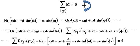 (10)
(10)
Once Na and Nd are known, then the vertical reaction in the front tires (Nd) is determined, proposing the balance of forces in the vertical axis:
 (11)
(11)
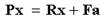
The horizontal component of the total draft force of the aggregate Pt is determined by raising the balance of forces in the direction of the x-axis:
 (12)
(12)
The components Rxi, Fa, Fd and Ft are determined from expressions 1, 4, 5 and 6.
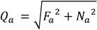
The draft force demanded by the implement, without considering the draft required by the tractor itself, is determined as:
 (13)
(13)
where:
 (14)
(14)
 (15)
(15)
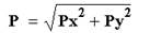
The angle that forms the draft force of the implement with the horizontal will be given by:
 (16)
(16)
The set of developed equations were programmed using the software Mathcad 2000 Professional, obtaining the behavior of the different parameters depending on the position of the support wheels of the implement, as well as the position of the instantaneous center of rotation π and the angle of the wedges of the implement. The program was evaluated by entering the following data, which correspond to the aggregate under study:
Average specific resistance: Ke = 90 kN/m2;
Transverse area of soil corresponding to each tillage unit:
Angle of sliding friction soil-steel: φ = 30.960;
Angle of the wedges with the horizontal: α = 200; 300; 400;
Weight of the implement: Ga = 3.468 kN;
Weight of the tractor: Gt = 71.15 kN;
Coefficients of rolling resistance of the wheels :
µ a = 0.24; µ d = 0.17; µ t = 0.14;
Wheel radius: ra = 0.158 , rt = 0.875 y rd = 0.656
Horizontal coordinate of the center position of the implement support wheel:
x = 0 … 2 m;
x π = 0.60; 1.20; 1.80 m; y π = 0.25; 0.50; 0.75 m;
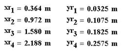
x t = 1.338 m; x dt = 2.887 m; x gt = 1.094 m; x ga = 0.525 m;
ANALYSIS OF THE RESULTS
As a result of the evaluation of the system of equations developed, aided by its computer programming in Mathcad 2000 Professional, the behavior of the main output parameters was obtained according to the position of the support wheels of the implement, the angle of the wedge and of the position of the instantaneous center of rotation of the suspension system, which is shown in graphic form in Figures 5, 6 and 7.
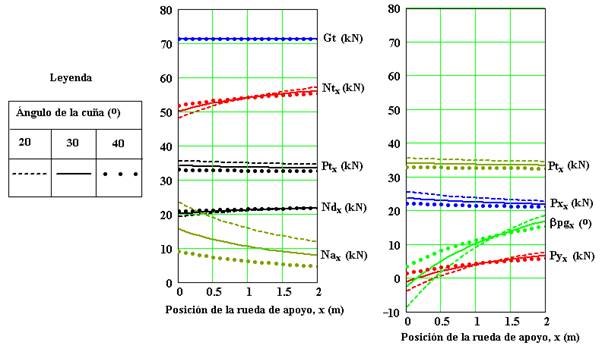
FIGURE 5 Variation of the different parameters depending on the position of the support wheel and the angle of the wedge.
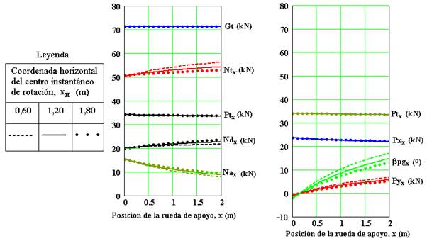
FIGURE 6 Variation of the different parameters as a function of the support wheel position and the horizontal coordinate (xp) of the instantaneous rotation center of the suspension system.
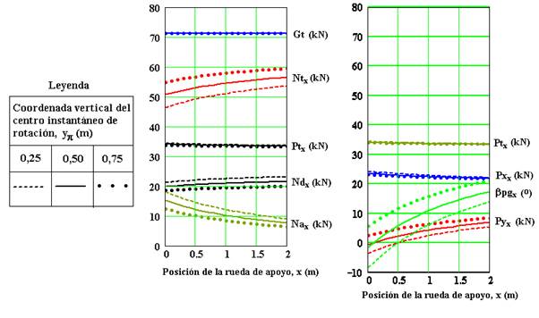
FIGURE 7 Variation of the different parameters depending on the support wheel position and the vertical coordinate (yp) of the instantaneous rotation center of the suspension system.
From the graphs, it can be seen that, as the center of the support wheels moves away with respect to the attachment points of the suspension system, the magnitude of the vertical ( Py ) component of the draft force and its angle ( βp ) with respect to the horizontal are increased in all cases. That affects the increase of the vertical reaction ( Nt ) on the rear wheels of the tractor, at the expense of a discharge of the support wheels of the implement, decreasing Na. In all cases there is also an increase, although slight, in the vertical load (Nd) on the front wheels of the tractor. It is of interest to note that, for positions of the support wheel very close to the suspension points to the tractor, the vertical component Py of the draft force can change sign and the angle βp can be negative, losing the suction condition or penetration of the implement. This situation is more pronounced for smaller values of the angle α of the wedge and for a small height and π of the instantaneous center of rotation of the suspension mechanism. It also highlights the fact that the horizontal position xπ of the instantaneous center of rotation (Fig. 6) has less influence on the variation of the different parameters evaluated, compared to the vertical position yπ, whose variation causes significant variations in the values of the vertical reactions of the soil on the wheels, both of the tractor, and of the implement. The equipment studied presents, as a proposal of the designers, a position of the support wheel x = 1.60 m, as well as an angle of the wedge α = 300, which is considered acceptable according to the analyses carried out. From Figure 5, it is observed that in this case, adequate values of the vertical load Nt are obtained in the rear wheels, in the order of 56 kN, sufficient to guarantee power transmission during rolling under normal soil conditions. On the other hand, the load on the front wheels (of the order of 10 kN in each wheel), makes it possible to guarantee a stable direction of the tractor. Likewise, it is appreciated that in this case, the vertical load on the implement support wheel does not reach values of the lowest, in the evaluated range and that at the same time an adequate suction of the implement is guaranteed, being Py of the order of 6 kN and βp close to 150.
CONCLUSIONS
A mechanic-mathematical model of the system of forces acting on an aggregate formed by a tractor with rubber wheels with rear traction and a tillage implement having four staggered shanks with “V”- shaped blades is elaborated. Equations obtained were programmed based on Mathcad 2000 Professional software, which allows replacing the cumbersome traditional method of constructing force polygons and rays. As result of the model application, the influence of the position of the support wheels of the implement, the angle of the wedges of the tillage units and the position of the instantaneous center of rotation of the tractor suspension system on output parameters is obtained. Such parameters are the vertical reactions of the soil on the tractor wheels and the support wheel of the implement, as well as the magnitude and direction of the draft force, allowing evaluating the conditions of stability of the aggregate and suction of the implement. The variation of the vertical position yπ of the instantaneous center of rotation of the suspension mechanism caused the most significant variations in the values of the vertical reactions of the ground on the wheels, both of the tractor, and of the implement. Likewise, it was determined that for positions of the support wheel very close to the points of suspension to the tractor, a change of sign occurs in the vertical component Py of the draft force, losing the condition of suction or penetration of the implement. This situation is more pronounced for smaller values of the angle α of the wedge and for a small height and y π of the instantaneous center of rotation of the suspension mechanism.

