


 Serviços customizados
 texto em
  Inglês (pdf)
 Artigo em XML
 Referências do artigo
 Enviar este artigo por email
 Citado por SciELO
  Similares em
SciELO
Similares em
SciELO 
 Permalink
INTRODUCTION
The tillage tool-soil interaction is characterized by two phenomena: forces arisen in the soil-tool interphase (lateral and vertical draught forces) and displacement of soil particles (Ani et al., 2014).
An important part of the researches related with tillage tool-soil interaction has been focused on developing simulation models to predict the cutting forces under different soil conditions, tool geometry and operation parameters (Armin et al., 2014).
Significant effects of these parameters and conditions in draft forces have been experimentally demonstrated in several research works. Nonetheless, the experimental studies are expensive and their results depend on the precision of measurement instruments.
The Finite Element Method (FEM) has been utilized to a great extent at international level in the soil-tillage tool interaction, because of its potential to describe it in three dimensions (Herrera, 2006, Armin et al., 2014 and Tagar et al., 2015).
Many investigations of soil-tillage tool interaction by the finite element method have been realized focused to develop models, in two or three dimensions (Swick and Perumpral (1988), Mouazen and Neményi (1999), Abo et al.(2003, 2004), Brown (2012), Bentaher et al.(2013), Armin et al.(2014, 2015, 2016), Elbashir et al.(2014), Neisy (2014) and He et al.(2016). They have been both linear and non-linear models, elastic, plastic and elastoplastic models to predict the soil efforts on farming tool, the geometry influence in cutting forces as well as the energy consumption. Most of these researching was realized at small tool displacements and lower cutting velocities.
Dynamic simulation models of soil-tillage tool interaction by the finite element method have been developed by Swick and Perumpral (1988), Dechao and Yusu (1992) and Abo et al. (2003) keeping into account the cutting velocity, stresses level and acceleration.
When the soil-tillage tool interaction is analyzed as a dynamical process, it is taking into consideration the possible inertia effects regarding to the influence of soil mass and deformation grade. In such cases, the time is included in the formulation of the constitutive model (Herrera, 2006).
The goal of this study was to develop a 3D dynamic simulation model of the soil-tool farming interaction process to analyze the tool moving across the soil, the distribution and magnitude of stresses and strains, as well as the cutting forces.
METHODS
Soil Model. In this study the soil-tool interaction is modeled by the yield Drucker-Prager linear function, which may be expressed as:
Where:
t: is the deviatory effort and can be calculated by:
K: is the ratio of the yield stress to the compression yield stress in triaxial test
Where:
p is the normal effort acting on the soil, defined as:
Q is the Von Misses equivalent stresses, calculated by:
r 3 is the third invariant of deviatory efforts
The cohesion d, when the hardening is defined by the same, is calculated as:

FIGURE 1 Yield criterion of the Extended Drucker-Prager model. a) Southern plane b) Principal stresses plane. (Hibbit, 2008).
Soil Properties. The soil was classified as red Ferrallitic, according to Second Genetic Classification of Soils in Cuba (Hernández et al., 1975), as Oxisol (Cid et al., 2011), as Rhodic Ferralsol (Hernández et al. 2015). Its density was 1200kg.m-3, its plasticity ratio was 36,2% and its organic matter content was 2,7%. The modulus of elasticity was determined by the slope of a tangential line of a stress- strain curve in straight section.The Poisson rate was determined by:
The cohesion and internal friction angle were determined by the Mohr graphical solution. According to the texture soil triangle according García de la Figal (2013), the soil in study is classified as no much dense.
Table 1 shows the properties and parameters of soil required for the FEM model.
TABLE 1 Properties and parameters required for the FEM model
| Property or parameter | Symbol | Dimension |
|---|---|---|
| Friction internal angle | φ | 33º |
| Modulus of elasticity | E | 5 000 000 Pa |
| Poisson ratio | υ | 0,394 |
| Flexion stress | σ f | 130 000 Pa |
| Dilatancy angle | ψ | 0º |
| Cohesion | d | 15 000 Pa |
| Shear resistance | τ | 200 000 Pa |
| Shear modulus | G | 1 793 400 Pa |
| Type of soil | Lineal elastic | |
| Traction limit of soil | σ t | 30 000 Pa |
| Compression limit of soil | σ c | 500 000 Pa |
| Elastic limit of soil | σ e | 42 000 Pa |
| Soil humidity | H | 27% |
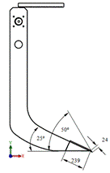
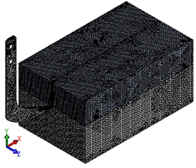
Finite Element Model. A 3D dynamic simulation model in finite elements of the soil-tillage tool interaction was developed using the Solid Works design software. The tillage tool (vibratory curved bent leg) with logarithmic profile formed it. A vibratory mechanism with swimming masses was added to it and it is considered as a discreet rigid body (Figure 2).
The soil block was deformable in the bent leg interaction (Figure 3), it had a length (L) of 2m, width (B) 1m, height (H) 1m. The width of the soil prism chapped by the tool coincided with the chisel width (b=0,041 m). The working deep of the bent leg (D) was 0, 40 m and the cutting angle was 25 grades.
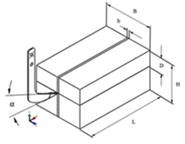
The growing of the chapped soil prism dimensions beyond the assigned does not affect the cutting forces (Bentaher et al., 2013) (Ibrahmi et al., 2014). The soil tool interaction was modeled tangential to the attack surface with contact model surface to surface.
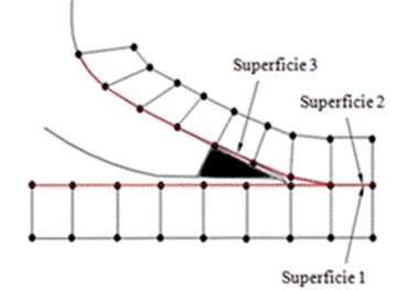
Contact Modeling. In the block soil cutting process, the contact modeling is complicated because one of the surfaces (soil prism surface) does not exist initially in the model; it is formed as the process goes by (Figure 4)
The part of block soil converted in prism slides over the tool attack surface, which causes a contact zone with high friction between both surfaces and high stresses.
The contact problems are modeled by finite elements using basic contact surfaces (Rodriguez, 2001).The prism formation occurs gradually with the tool displacement towards block soil. Surface 1 becomes the tilled surface and surface 2 contacts surface 3 (attack surface of the tillage tool).
As the surface 3 is formed, the contact elements of this surface are activated as a contact surface, which will displace over the sliding line defined by them. They build up a contact surface between two deformable bodies (Figure 5).
Loads and Boundary Conditions. The model boundary conditions were established in function of performing loads. Gravity acceleration (9,81 m·s-2) and atmospheric pressure (101325 Pa) act on the block soil and it has restricted movement of its lateral (axis Z) and lower (axis Y) parts. The tillage tool moves at constant velocity (0,85 m.s-1) in the positive direction of axis X (Figure 6) with frequency of the vibratory mechanism of 14 Hz. The draft force applied was 15 000 N. The chapped prism moves over the chisel attack surface.

Mesh of Model. The general model mesh was realized with maximum element size (e) of 0,03 m, minimum size of 0,006m and Newton Raphson iterative method was utilized. The surfaces in contact, both tool and chapped soil prism, were meshed applying mesh control, with element size of 0,004 m (Figure 7).
RESULTS AND DISCUSSION
The results of the tridimensional simulation model presented provided information regarding cutting forces, stresses, distortions and displacements, both soil and tool. The model was able to simulate the vibratory bent leg's displacement and vibrations with selected frequency and amplitude, as well as the chapped soil prism advance on the chisel surface.
Forces in Tillage Tool. Figure 8 shows the direction and magnitude of the resulting forces from the tillage tool- soil block interaction and from the advance of the tillage tool across the soil.

As it can be observed, the biggest values of the draft force are on the tip (Fx=-1350 N) and on the attack surface of tillage tool (Fx=-3890 N), in the direction of the tool movement and they have a minus sign. These values are similar to those obtained by other authors in previous researches (Moeenifar et al., 2014).
The magnitude of resulting forces is determined by the type of soil utilized in simulation (Davoudi et al., 2008). The maximum draft force (Fx) is considered as the necessary force to break the soil block in front of the tool and as the soil resistance when it is chapped (Elbashir et al., 2014b).
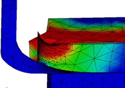
Stresses in Tillage Tool. Figure 9 shows the progress of von Misses stresses when the scarifier bent is tilling the soil. The model is able to simulate the soil-tool interaction process in adequate form.
The stresses increase during the initial contact phase between tool and soil and they are subsequently stabilized, which agrees with studies realized and experimental data published by other researchers (Mouazen and Neményi, 1999b; Abo et al., 2004b; Bentaher et al., 2013b; Chen et al., 2013 and Ibrahmi et al., 2014). These results show the validity of the implemented model.

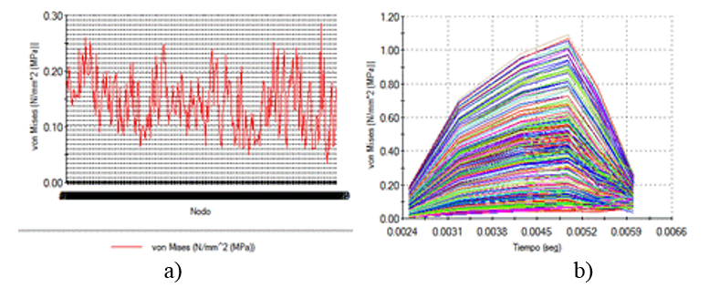
Normal Stresses in X Direction at the Tool Tip. When the contact with soil starts, the normal stresses in X direction at the tool tip (Fig.10) have a minimum value of 0,035 MPa, growing in asymptotic mode (Mouazen and Neményi, 1999b). As the bent move towards the soil block, the stresses reach a maximum value (0,28 MPa), decreasing again until they stabilize in an average value (approximately 0,15 MPa). It is mainly due to the oscillating movement of bent and to the soil resistance.
Normal Stresses in Attack Surface. Normal stresses in attack surface (Figure 11) grow to a minimum value of 0,14 MPa until reaching a maximum value of 8,55 MPa, after are stabilized approximately in 3,92 MPa. This stresses average values are bigger than the tool tip because of the great contact area existing between this surface and block soil.
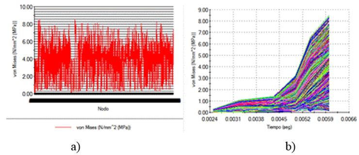
FIGURE 11 Normal stresses in the X direction in the attack surface of the tool. Statics in nodes b) dynamics.
Model Validation. To validate the implemented simulation model, the validity of predefined fault surfaces, according to Abo et al. (2003a) in vertical plane (XY plane), was examined. The strain stresses distribution at zero displacement of the tillage tool (Figure 12a) and the tillage tool displacement of 300 mm (Figure 12b), were analyzed.
The continuous outlines of the strain stresses distribution along the predefined fault surfaces (Figure 12b) reveal the validity of them when the gravity force is applied on the model.

CONCLUSIONS
A dynamic 3D simulation model of the soil- narrow tillage tool interaction using the finite element method was implemented.
The Drucker-Prager elastoplastic constitutive relation model utilized in simulation was able to predict the soil behavior when it interact with the tillage tool.
The predefined fault surfaces concept showed to be adequate for the 3D modeling of the soil-tillage tool problems.
The values of the model resulting forces were similar to those found in the consulted literature and bigger in the work surface of the tillage tool.
The values of resulting stresses of the simulation agree with the result of other authors in previous researches.

