


 Servicios personalizados
 texto en
  Inglés (pdf)
 Articulo en XML
 Referencias del artículo
 Enviar articulo por email
 Citado por SciELO
  Similares en
SciELO
Similares en
SciELO 
 Permalink
INTRODUCTION
To predict wear and behavior of tools and complex mechanical systems of agricultural machinery, several hundred and thousands of cycles that operate during the process have to be simulated (Hemanth, 2011). However, simulation through computational tools is closely linked to the development of numerical methods and specialized software, which take into account the behavioral equations that govern the process and the main development peculiarities of the phenomenon.
The advances in the development of simulation programs, added to the constant increase of the calculation capacity, have allowed studying the mechanical behavior of the tribological pairs in a more or less simple way, and from these results, to implement the incorporation of models of wear. Thus, in this field, authors such as Xie et al.(2005), Hernández et al. (2007),Negrín et al. (2008), Hemanth(2011),Pérez et al.(2014), Saucedo (2014), Zuo et al.(2014), Da Silva (2016), Attanasio et al.(2017) and Ramadhani (2018), have executed important works of wear simulation using the Finite Element Method. At the same time, other authors, including Hernández et al.(2005), Kanavalli (2006),Ding et al. (2008), Cruzado et al.(2010, 2013), Hernández and Riera (2014), Zegatti (2016) and Goreham and Brown (2017), have made significant contributions to the wear simulation in FEM using the ABAQUS computer program, through the implementation of the UMESHMOTION subroutine.They have used the tool calledLangrangeana-Euleriana Arbitrary Adaptive Mesh ("ALE MallaAdaptativa") that allows implementing the Archard wear model and the Dissipated Energy model, which currently have a great acceptance in the analysis of this phenomenon.
On the other hand, Recarey et al.(2001), Burrel(2003),Gutiérrez and Fuentes (2007),Sánchez et al.(2009, 2014), Champagne et al.(2014) and Perazzo et al. (2016), have carried out important wear studies using the Discrete Element Method, which is a numerical method capable of specifying the behavior of geometrically defined media by particles.
Similarly, Oñate et al. (2005), Ramalho (2008), Nitka et al.(2011), Stransk and Jirasék (2012),Morales (2013), Taforel et al.(2015) and Sun et al. (2016), have obtained results that show that the combined FEM-DEM methodology is an efficient tool to analyze the wear behavior due to fracture. That is because, in most of these problems, the phenomenon appears only in certain parts of the domain (contact zone) and the rest has a behavior that can be represented as continuous. Hence, the interest to model this type of problems with the method of discrete elements (DEM) for the area of wear and FEM for the rest of the domain, taking advantage of the benefits both methods offer.
METHODS
Wear patterns. The model of Archard is the best-known and used wear model in academic and engineering environments to estimate wear on surfaces and parts. According to Zegatti (2016), this model considers that the volume of material removed (V), obtained from the interaction of two bodies, is directly proportional to the normal load applied to the body (P) and to the sliding distance (s), and inversely proportional to the hardness of the material (H). A dimensionless coefficient (K), called the wear coefficient, is introduced to take into account different materials, geometries and applied loads. The ratio between this coefficient and the hardness is replaced by a specific wear coefficient (k), this being the only property of the material present in the Archard wear law represented in Equation (1).
This equation allows calculating the global wear volume, however, to use the analysis programs by finite elements and discrete elements it is necessary to estimate the wear locally. In this sense, McColl et al. (2004) cited by Zegatti (2016), developed a modified version by applying Equation (1) locally to an area dA and for an increase in sliding distance ds. Then, bydividing both sides of the equation by dA, Equation (2) is achieved, obtaining the infinitesimal wear height (dh), and the normal contact pressure observed on the contact surfaces p(x).
When this equation is applied in the FEM, the infinitesimal height (dh) represents the nodal depth of the material that will be removed (Δh), after traveling a relative sliding distance (Δs). In the absence of a method to calculate the wear coefficient locally, this author considers that the local wear coefficient is the same used in the determination of the global wear volume, there being no great implications in the results on account of this consideration, so therefore, the formulation adopted for use in the FEM analysis is presented below.
Finally, Equation (4) is the formulation currently used to compute the nodal depth of wear at each increment, affected by the wear accelerator (ΔN), which uses the results generated in a cycle to estimate the wear for a greater number of cycles, reducing the computation time and not generating instabilities or great divergences in the results.
The Dissipated Energy model takes into account the energy consumed in the wear process, since a specific amount of energy is necessary to remove a certain volume of material. Here it is considered that the volume of wear (V) is obtained by multiplying the dissipated energy by the accumulated friction in the interface (ΣEd), by a wear coefficient of the accumulated energy (α) as shown in Equation (5). This energy is obtained by calculating the generated work by the tangential force (Q) along the traveled distance as seen in the Equation (6).
As in the Archard model, the dissipated energy can be analyzed locally to obtain the nodal depth of the material that will be removed, leaving the necessary formulation expressed in Equation (7), where the only difference observed between the two models is in the inclusion of the friction coefficient, whenever
RESULTS AND DISCUSSION
Modeling in FEM. To simulate the process, it is necessary to verify the correct positioning of the bodies in contact, to guarantee that the initial interaction between them is carried out successfully. Besides,it is necessary to define the properties of the material and the contact properties, where the slave and master surfaces area detailed, just in the region where the contact willoccurin fact, so that unnecessary computational time is not required. In the contact zones (Figure 1), where the most critical values of the tension, deformation and pressure distribution fields are verified, a more detailed refinement of the mesh is performed.

In ABAQUS program, the implementation of the wear model is carried out through the UMESHMOTION subroutine (Figure 2) by means of the ALE adaptive mesh, which is used to improve the convergence of the mesh in simulations where large distortions in finite elements are observed. By means of a mesh remapping, the adaptive mesh repositions the nodes for a more appropriate position, improving the convergence and combining the characteristics of a purely Lagrangean analysis and a purely Eulerian one, which allows a high quality mesh to be obtained during all the simulation, the same when large deformations or material losses occur.
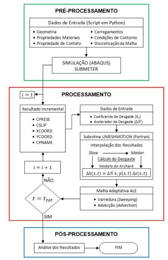
The process of implementation of the local wear begins in the pre-processing, where the modeling of the problem is carried out. In this stage, the geometry, the properties of the material, the properties of the contact, the loads, the conditions of contour and the discretization of the mesh are input data for the creation of a script in the Python language and, by means of this code, the simulationstarts. Then,it is expected that it reaches the step where the application of the displacement cycles begins. Immediately after the first increment converges, the results obtained in each node are used to serve as data input to the subroutine. Together with these results, the local wear coefficient (kl) and the wear accelerator (ΔN) are also used as input data for the subroutine, written in FORTRAN programming.
The nodal displacement referring to wear is applied in the normal direction to the surface on which the node is located. To calculate that depth of wear, the modified Archard method presented by McColl et al. (2004), is used. With all these computed values, the adaptive mesh ALE performs the processes of sweeping and advection to make effective the remappingof the mesh. After this stage, new values of the field of distribution of stresses and distribution of contact pressures are recalculated according to the configurationused. Finally, in case that the simulation time is less than the total expected time, the next time increment is performedand, if not, the simulation is finished and the data are available for the analysis of the results Zegatti (2016).
Modeling in DEM. To implement the wear model in a DEM code and to model the loss of material of the piece from the information of the Archard model, it is necessary to specify the information of the wear patternto be visualized. Because of that, it is necessary to develop an own DEM code that grants the required flexibility for this type of specific application (Perazzo et al., 2016).
The discrete element method is implemented as a cyclical algorithm, where the laws of motion of each particle, a law of force-displacement in each contact and a constant updating of positions are applied. From the knowledge of the position and velocity of the particles, the contacts of different particles are updated and the modified Hertz contact model is applied to determine the reaction forces (Hu et al., 2010). The Archard wear model takes information on the speeds and forces to predict the volume loss associated with abrasive wear on the machine element. With the information of the forces and torques, the new speeds and positions are calculated using a direct method of temporary integration.
The constitutive model of contact between the particles of the medium is formulated taking into account that in the normal direction of contact, they will have a viscoelastic reaction that is given by the inclusion of the normal stiffness (kn) and the viscous constant in the normal direction (Cn). In the tangential sense of the contact, the constitutive model comprises an elastic reaction of the medium represented by the tangential stiffness (k T ), the viscous constant in the tangential direction, in addition to the action of the interparticle friction given by the Coulomb coefficient (μ)that, the internal friction of the medium,will be taken as data. In the case of the constitutive model of contact between the particles of the medium and the tool (Figure 3), it is formulated in a similar way, with the difference that the friction coefficient to be taken as data corresponds to the external friction related to the average friction -tool.
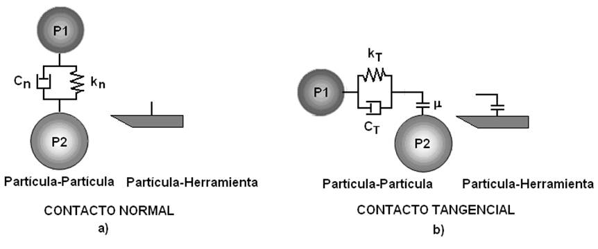
FIGURE 3 Constitutive models of contact, a) Among the particles of the medium, b) between the medium particles and the tool (Sánchez et al., 2014).
The action-reaction forces that act among the particles of the medium during the interaction or between the particles of the medium and the tool (Figure 4) will be determined from Newton's third law. The determination of the contact forces (Fn) and (F T ) depend on the equilibrium equations, either between the particles of the medium, or between the particles of the medium and the tool.
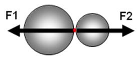
FIGURE 4 Representation of theaction-reaction forces that act among the particles of the medium during the interaction or between the particles of the medium and the tool(Sánchez et al., 2014).
The constitutive models of contacts presuppose the existence of both elastic and viscous damping. Therefore, the normal force (Fn) will be composed of a normal elastic force (Fne) and a normal damped force (Fnd).
The breaking of the contacts between particles is mainly due to the application of external loads to the system, the action of the volumetric forces and the reaction forces that generate the collisions between particles. This rupture occurs once the magnitude of the maximum cohesive force of the contact in the tangential or normal direction is exceeded (

FIGURE 5 Normal contact forces versus relative displacement in the normal direction and normal damping force versus relative velocity in the normal direction (compression or traction) (Recarey et al., 2001).
Combination FEM - DEM. Coupling the FEM and the DEM is a possibility to take advantage of the benefits presented by both methods,considering the problems that cannot be approached by only one of them. The idea is to model part of the domain with DEM, for example, where a granular medium is present, and the other partwith FEM, where the use of simple triangular or tetrahedral elements to model the continuous domain is very useful from the point of view of simplicity of geometry. Examples of this are the problems in which there is interaction of solids and structures with granular media (Oñate et al., 2005).
According to Morales (2013), a discretized continuous medium with FEM can be seen as a discretization with DEM with virtual elements of FEM as shown in Figure 6.
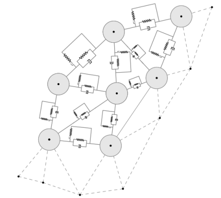
Given the main characteristics of both methodologies, it is convenient to start with the formulation of FEM finding displacements, tensions, deformations and all those variables of interest. Then particles with center in the nodes i,j,m and their respective radios,ri, rj,rm, are assigned to relate the contact force between each pair of particles; that is, the contact force of DEM is modeled at each edge of the triangular element of FEM (Figure 7).

To model this contact force from the properties of FEM, each element of the FEM discretization has an associated elementary stiffness matrix. Then, known the rigidity that each edge provides to the FEM formulation, it is possible to model the force of contact in these. To determine which edges will suffer some damage, a breaking criterion is adopted based on the evaluated stresses and deformations in all edges of the discretization. When the breaking criterion is reached, particles are created in their nodes and their corresponding radii are assigned; then, it is necessary to eliminate the contribution that this edge contributes to the rigidity matrices of those elements that share it or of that element that contains it when this edge is at the frontier of the study domain (Morales, 2013).
Finally, the elementary matrices whose edges have suffered some damage in the global stiffness matrix are assembled, passing the damage that each edge undergoes to the global system, in such a way that in the next iteration of the simulation process, a domain with a located damage is considered. In the case that dl = 1, the domain suffers a fracture, also localized.
CONCLUSIONS
The use of UMESHMOTION subroutine in FEM programs allows local wear to be computed after each increment of time and not after an entire displacement cycle and to perform the meshing update, it is not necessary to stop the simulation and restart it again.
One of the main points to be addressed in the numerical simulations carried out by means of the discrete element method is that it allows the material to be brought to a breaking stress, and thus be able to simulate this breakage and wear.
The combination of finite elements and discrete elements defines a powerful tool that is presented as an idealization that takes the strengths of each method and groups them into one, where the discretization of the particles is done using the finite element technique, while the modeling of the contacts between each particle is done using the discrete element technique.

