


 Servicios personalizados
 Inglés (pdf)
 Articulo en XML
 Referencias del artículo
 Enviar articulo por email
 Citado por SciELO
  Similares en
SciELO
Similares en
SciELO 
 Permalink
Introduction
Compact heat exchangers are devices that transmit heat between two fluids with different temperatures. They are essential components in many processes that are part of our daily life. Some of the most common uses include air conditioner condensers and evaporators. There are several configurations and enhancement heat transfer techniques used in this type of equipment, such as continuous fins, wavy fins or interrupted fins (Kays & London, 1984).
Louvers fins offer great advantages over continuous fin designs Wang (2010). Each louver generates a new boundary layer, with very little development length, thus decreasing its average thickness and reducing the resistance to the passage of heat. This increases heat transfer and it results in a reduction of the size of the heat exchangers, and thus reducing its weight and the cost of the materials (Li, et al., 2019b).
Louvers fins are very effective passive intensification techniques in terms of heat transfer, with high values of the heat transfer coefficient. On the other hand, they generate large pressure drops in comparison with other intensification technique (Li, et al., 2019a). In Wang (2010), it is argued that in the heat exchanger field, 90% of the patents generated until 2010, are referring to interrupted fins.
Salviano et al. (2014) performed a numerical study of optimization of the position and angle of attack of vortex generators (VG) on the fins of compact heat exchangers with circular tubes in alternating arrangement. The simulations were performed for turbulent flow, setting the Reynolds number to 1400 based on the passage between fins. The results indicated that the position and angles of the VG that are near to tube 1 and to tube 2 were not necessarily the same.
Jang & Tsai (2011), suggested a method to find the optimum angle of inclination of louver fins in a finned heat exchanger by using the simplified conjugate gradient method (SCGM) and a Computational Fluid Dynamics (CFD) model. Optimum louver angle values ranged from 15º to 45º for Reynolds numbers ranging from 100 to 500 (based on spacing between fins). For angles below 30°, the larger louver angle is, the greater are the Colburn factor (j) and the friction factor (f). However, for angles above 30°, the larger louver angle is, the greater is the value of f, while the Colburn factor did not show appreciable changes.
Huisseune, et al. (2013a b), investigated numerically the influence of five important design parameters on the thermo-hydraulic behavior of the compact heat exchanger with circular tubes and louver fins. They investigated three levels of each control parameter (fin passage, louver angle, delta wing type, angle of attack, VG height ratio to channel height and delta wing aspect ratio). At high inlet velocities, the performance was determined mainly by the louver fins, (the angle and the passage of the louver fins). At lower velocities, the geometry of the VG increases its influence on the thermo-hydraulic behavior and it was incorporated as a parameter in the optimization.
Ameel, et al. (2013), developed a numerical optimization of a louver fin heat exchanger with variable louver angles. A geometry was analyzed that includes circular tubes and louver fins with angles that vary individually for each louver fins. To establish the initial models to be studied, the Latin hypercube sampling (LHS) technique and two Kriging models were used, one for pressure drop and one for heat transfer. The main conclusion of this research was that, the louver angle, varied independently, is not a solution to obtain better thermo-hydraulic behavior. The Colburn factor was increased only 1.3% for the same friction factor as the baseline model.
Their results agree with Salviano, et al. (2014), both agree that the combination of the substitute model and the optimization procedure proved to be a powerful tool in the research dedicated to the heat transfer enhancement using VG.
Dezan, et al. (2016); and Damavandi, et al. (2017), used an optimization procedure to maximize heat transfer in compact heat exchangers with louver fins and VG. The NSGA-II (Nondominated Sorting Genetic Algorithm) is used as optimization method combined with artificial neural networks. Compared to the geometry used as reference (exchanger with fins without VG). Finally, the NSGA-II algorithm obtains the optimal Pareto set by using the input data of the neural network. By combining CFD, neural networks and the NSGA-II optimization algorithm, very useful and valuable results were obtained; that, otherwise, could not be achieved without the joint use of these techniques.
Despite the large number of works found in the literature on louvers fins with vortex generators, further work needs to be done. Particularly, the geometric parameters of the VG need to be optimized because they are strongly related to the flow pattern in a heat exchanger. There are no studies found in the literature referring to inclined vortex generators. This work aims to determine the influence of the tilt angle of the VG on the thermo-hydraulic performance of louver fins with circular tubes, by using numerical simulations and metaheuristics. These results would make it possible to create compact heat exchangers smaller, lighter and use less material.
Materials and methods
Figure 1 shows the main parameters that characterize the design of louver fins. Each louver section between tubes of the same row is comprised of louver half of entrance and half of exit, in addition to two louver fins on each side of the turnaround louver. Delta-winglet vortex generators are punched in the fin, downstream of each tube. In Figure 1 it can be seen how the angle of inclination of each VG will be varied in this study. The references made in this research to any dimension of the VG will be specified with a subscript. That is, for references to the inclination angle of the vortex generator 1 will be used δ 1, while δ 2 is used for the inclination angle of the vortex generator 2 (Figure 2).

Table 1 reflects all the values of the geometric parameters described in Figure 1. Likewise, the range of variation of the angles that will be studied is presented in this table too.
Table 1 - Geometric dimensions of the model.
| Description | Nomenclature | Value |
|---|---|---|
| Longitudinal pitch [mm] | L | 13.6 |
| Transversal pitch [mm] | S t | 8.8 |
| Fin pitch [mm] | Fp | 1.71 |
| Louver angle [º] | α | 35 |
| Fin thickness [mm] | F t | 0.1 |
| Tube diameter [mm] | D | 6.75 |
| Louver pitch [mm] | Lp | 1.5 |
| VG tilt angle [º] | δ | 30-140 |
| VG longitudinal position [mm] | Δx | 0.5 D |
| VG transversal position [mm] | Δy | 0.3 D |
| VG angle of attack [º] | β | 35 |
| VG height [mm] | h | 0.9Fp |
| VG base [mm] | b | 2h |
| Fin Material | aluminum |
The study is carried out in a model with two rows of tubes in alternating arrangement. The louver fin geometry under analysis has typical dimensions, which are recurrent in the literature (Qian, et al., 2018; Dezan, et al., 2019). The VG is located at 0.3D measured from the center of the tube in the spanwise direction and 0.5D in the streamwise direction as can be seen in Figure 1. This location is optimal based on the results obtained in a previous study conducted by Ameel, et al. (2013), for a model with similar dimensions to the one studied in this work.
Numerical model
The governing equations used will be the continuity equation, the momentum equations in each of the axes, and the energy equation. These equations in laminar regime and steady state can be expressed in the same order as they are mentioned, as follows:


The solution of Eq. 1, 2 and 3 is performed on a discretized computational domain, which is shown in Figure 2. In this figure, we can observe the boundary conditions used in each region of the domain, as well as the fin and the direction of the main flow.
The fin is located in the middle of the air channel. At the inlet, the domain extends 7 times the fin space to guarantee a uniform and one-dimensional flow pattern of the air flow at the inlet of the domain. The extension allows capturing the sudden contraction effect at the inlet. On the other hand, the domain extends about 20 times the diameter of the tube in the direction of flow to consider the sudden expansion of the flow at the outlet of the channel. It is necessary to avoid reverse flows, which are incompatible with the boundary condition used at the outlet. The domain extensions are according to those frequently used in the literature (Huisseune, et al., 2013a; Moreno, et al., 2020).
On both sides of the domain, a boundary condition is imposed by considering the symmetry in the airflow and in the heat flow through the fin. The upper and lower faces of the domain are considered periodic; this assumes that the value of every magnitude is repeated every one step. Here, the step is equal to the fin pitch F P :

Where γ is any magnitude (u,v,w,…)

The flow will be considered incompressible, in steady state, without viscous dissipation, inside the laminar regime. The fluid and solid properties are constant. The numerical simulation will be carry out in three-dimensional coordinates, with velocity and temperature fields uncoupled. The airflow velocity and temperature profile at the inlet domain are considered uniform. The air temperature at the model inlet is 293K and the tube wall temperature is 323K. The inlet velocity is 1.5m/s, and Reynolds number is 350 based on the velocity in the minimum cross-sectional flow area and hydraulic diameter.
The fin in the central region of the domain is taken as a solid, while the channels on and under it are considered as fluid regions. The necessary boundary conditions include the temperature in the tube wall and the parameters of the fluid at the inlet. The temperature of the inner tubes will be considered equal to the refrigerant temperature circulating inside the tubes. In doing so, the value of the heat transfer coefficient on the inside of the tube is disregarded.
A non-slip condition, impermeability and conjugate heat transfer were considered on the fin surface and on the vortex generators surface.
Data reduction
The determination of temperature and velocity fields is the main result of the numerical simulation process. For each value of the inlet velocity, the inlet and the outlet temperature of the air passing through the channel formed between two subsequent fins can be obtained. The procedure shown below was applied during the model validation too. The heat transferred in the fin is calculated as:

The mass flow m is determined as result of the application of the continuity equation, according to:

Considering a high value of the heat transfer coefficient inside the tube, the inner resistance to the heat flow is neglected. Then, the temperature of the inner wall of the tube is considered constant. Under these conditions, ΔTlog is expressed as:

The determination of the efficiency of the surface  is a function of the fin efficiency
  , which is obtained via the Schmidt (1949), method as it was also done by many other authors (Moreno, et al., 2020; Garelli, et al., 2019). An iterative process is necessary. Then the efficiency of the surface of the fin is:

The heat transfer coefficient in the airside is frequently considered as part of a dimensionless factor known as Colburn j-factor:

is the velocity in the minimum cross-sectional flow area. The pressure drop in the heat exchanger is considered by the part of the Fanning friction factor. This friction factor f, is calculated as proposed in Kays & London (1984).

The Reynolds number is calculated according to:

Grid convergence study
To guarantee the value of the obtained results, a mesh independence study is carried out. A model with VG with zero tilt angle was used in this study. This model will be used as a reference to assess changes in thermo-hydraulic behavior of models with VG at different inclination angles. Four meshes with different sizes of the elements that were simulated numerically using CFD were generated. For each model with a different density mesh, the values of j and f were determined. The results were considered independent of the mesh when the differences of values of j and f in successive meshes was about 1%. From this study and considering the balance between precision and computing time, it was decided to use the mesh that had a number of elements equal to 2 million elements, as shown in Figure 3.

Validation of the numerical model
To perform the validation of the results, a geometry similar to the one used in the work of Huisseune, et al. (2013b), was built. This geometry consisted of a heat exchanger of three rows of tubes with louver fins having two louvers on each side of the turnaround. The model was simulated by using CFD and following the same conditions, assumptions, boundary conditions and flow type to the regime in this research. In the reference work Huisseune, et al. (2013b), they present the results of the numerical simulation of the geometry, as well as the experimental values obtained by the author.
Figure 4 presents the results of the comparison using coefficient of friction factor and Colburn factor as a function of the Reynolds number based on the channel hydraulic diameter and the velocity in the minimum flow area region. Triangular points show the results obtained during this validation study. It is worth noting that the coincidence between the values obtained for j and f in this work and those obtained by the reference work is good enough to consider that the method used has been certified.

Results and discussion
In this research, the angle of inclination of the VG was analyzed. These were independently varied from 30º to 140º. The reference geometry, on which the modifications are made, has been widely studied by other authors Dezan, et al. (2019); and Moreno, et al. (2020).
To generate a random sample of the variables to be studied, the Latin hypercube method was used. It is well known as a successful method applied to the design of numerical experiments (Xu, et al., 2018; Wang, et al., 2018). A Latin hypercube divides a range of parameters into equally spaced values, with the particularity that two points never share the same value for any parameter.
The random sample of values was generated by maximizing the minimum distance between the points, choosing the best among 5 million random solutions. Figure 5 shows the result of the Latin hypercube sampling for this case study. For a system with two independent variables, only sixteen samples are necessary (Evangelaras & Koutras, 2017). Each point has a label containing the values of the tilt angles. In addition, an additional sample (red dot) was included because which corresponds to one of the geometries that will be used as a reference. The results will also be compared to fin of similar dimensions to the one studied but without vortex generators.

Once the methods used for data reduction are known and in possession of the geometries of each model meshed, the numerical simulations are carried out. The convergence in the simulations was obtained when the scaled residuals for the velocities and the continuity equation reached a value of 10-5, while the residuals in the case of the energy equation were allowed to decrease to values between 10-9 and 10-10. This configuration is similar to those used in other works Moreno, et al. (2020).
From the results of the numerical simulations in CFD, the Colburn and friction factors are calculated according to equations 9 and 10, respectively. Using the values of j and f determined above, a surrogate model is built by using a multiple regression technique, where the independent variables are the tilt angles of the VG of each row of tubes. The regression model obtained must have a statistically significant relationship between the variables with a confidence level greater than 95.0%. Otherwise, we proceed to increase the number of sample points that must be simulated using CFD (Figure 5).
For the Colburn factor, a correlation valued at R2 of 99.808% and a standard deviation in the residuals of 3.44x10⁻⁵ was obtained. Likewise, the correlation of f with an R2 of 97.6561% and a standard deviation in the residuals of 2.85x10⁻⁴ was obtained.
To increase the heat exchanged on the fins of a compact exchanger is one of the objectives of this research, but at the same time, without a high penalty in head losses. The iterative process of multi-objective genetic algorithms achieves an efficient approach to this end. They obtain the set of parameters that result in one or several models with a value of j greater than the reference, without significantly increasing f.
In order to obtain a Pareto set of solution (i.e. a collection of non-dominated solution with good trade-off between j and f), a multi-objective optimization approach based on metaheuristic was considered. Each solution in the metaheuristic search codifies two real values corresponding to the two tilt angles (each one in the interval [30º,140º]). The search process was conducted by using a real-coded multi-objective genetic algorithm available in MatLab 2018 (with a population size of 60 and 400 generations).
In addition, the previous results were compared to the solutions obtained by using a multi-objective hill climbing with a binary representation of both tilt angles. The result obtained with both metaheuristic approaches were very similar.
The results of the Pareto set were checked by using CFD. The errors in values of j and f, between the predicted ones and those calculated are lower than 2.4%. Figure 6 shows a schematic representation of the methodology followed in this research.

Among the solutions that result from the optimization process there are values that coincide with either maximizing or minimizing each of the objective functions individually. The model that least increases the pressure drop is the one with the rotation angles δ1 = 30º and δ2 = 130º. This result is to be expected, since for very low or very high tilt angles the projected frontal area of the VG is smaller, reducing significantly the pressure drag.
The genetic algorithms showed that the model with angles of rotation δ1 = 99.2º and δ2 = 98.9º achieves the maximum increase in j. When compared to the reference model (but without VG) the increase would be 7%, but it is only 0.6% when the comparison is made against the model with VG tilted 90º, (as they are generally arranged in most applications). Additionally, a slight decrease in the friction factor (0.5%) is observed.
As a method of comparison to determine how effective a geometry is, the criterion known as area goodness (equation 12) will be used, which is simply by determining how much the Colburn factor increases in relation to the increase in the friction factor, when they are compared by using the reference fin (subscript o) as a baseline.
All the models included in the Pareto set (as result of optimization) have values of area goodness greater than one, which shows how useful this type comparison tool can be, when pursuing objectives similar to those studied in this work. The model with tilt angles δ1=97.17 and δ2=106.6 ° would be the best according to this comparison criterion: a model that j increases more than 7% while f only increases by 5%.
In the composition shown in Figure 7, the particularities of the heat flow are analyzed. These graphs are made by integrating the heat flow in the direction transverse to the main flow in order to present them in a two-dimensional graph. The models of δ1=97.17 º and δ2=106.6º, and the model without VG were selected to show the main differences.

Figure 7a shows the area of low heat transfer coefficients associated with the recirculation zone or wake behind the tubes. In the region where the tube is located, there is a flow acceleration due to the reduction of the passage area (minimum flow area). The flow acceleration or tunnel effect produces differences between the heat transferred spanwise in the louvers. Note that the heat intensity transferred tends to be lower in louver fins as we move away from the surface of the first tube.
It can be seen in Figure 7-b how the inclusion of VG modifies the flow pattern on the surface of the fin. It is appreciated in the region where the VG are located that they are modifying the intensity of the heat flow transferred locally. In addition, a positive influence of the main vortex of the VG exerting its action on the wake area of the tube of the first row is noted, enhancing the heat transfer in this area. In the wake area of the tube of the second row it is observed that the effect is not so marked because the airflow reaches this region with a temperature much closer to the surface. With a lower temperature difference, the potential for heat transfer is limited. An interesting effect results from the presence of the VG of the first row; the presence of these VG reduce the action that the horseshoe vortices exert on the louvers of the second row and therefore, the heat transferred from them is diminished.
Figure 7-c shows the occurrence of peaks and valleys in the flow of heat that occur in the louver area. The peaks are associated with the development of new boundary layers starting from the leading edge of each one of the interrupted surfaces. Additionally, the influence of the horseshoe vortices developed on both sides of the tubes produces an intensified region that, added to the effect of the louvers, raises the amplitude of the heat flow peaks observed in Figure 7b. The vortexes generated by the surface facing the flow are responsible for the heat transfer enhancement on the fin.
Figure 8 shows a plane normal to the direction of the main flow at 12mm from the leading edge of the fin. In the Figure 8-a, it is presented the fin without VG, meanwhile below it is presented the model with VG having an angle 1 and angle 2 equals to δ1=97.17º and δ2=106.6º, respectively. The flow path lines and the vorticity values are superimposed on the same plane. In order to ease the understanding, the different vortexes were numbered. The region with the number 1 corresponds to the main vortex which is the strongest of the generated vortexes. The main vortex is created when the flow overcome the VG and the low pressure behind it make the flow wind on itself.
The region labeled with the number 2 corresponds to the corner vortex. Its influence is clearly noted in the Figure 7-b, because they are developed near to the channel between tubes and louvers and (in that way) they exert a higher influence downstream before to be destroyed by the louvers of the next row. In the region labeled with the number 3 appear the vortex created by the part of the louvers which connect it to the fin and (as a consequence) it appears in both models (Zhang, et al., 2020).
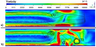
Fig. 8 - Path lines and vorticity values (s-1) superimposed for models with VG (b) and without VG (a).
In Figure 8, it is easy to observe the density of the path lines and the vorticity values. Both values are higher for the model with VG (b). It is a fact that a higher vorticity is related to the presence of a vortex which is transferring fresh fluid from the core of the channel to the region near to the surface. A higher temperature gradient produces a higher value of the heat transfer.
The total pressure drop is produced by two different sources, the first is caused by the pressure drag on the surfaces facing the flow; the second is produced by the viscous drag. Figure 9 presents the wall shear stress on the upper face of the fin. The model without VG is shown above, in the bottom appears the model selected as optimal as it was previously described. Vortex generators deployed on the fin surface always increase the pressure drop when compared to the pressure drop for the model without VG. However, it is known that the increase of pressure drop produced by VG is lower than the one produced by other enhancement heat transfer techniques.

The increasing pressure drop noted for the optimal model is mainly produced by a bigger area facing the flow. Then, it corresponds to the pressure drag. In this work the pressure drag created by the VG is approximately 5.8% of the whole pressure drop. Based on our results, it is clear the impact of the tilt angle of the vortex in the flow pattern obtained in heat exchangers.
Conclusions
In this paper, the influence of the geometric parameters of the VG in the flow pattern in a heat exchanger were studied. In particular, it was obtained several optimal tilt angles of the VG with good trade-off between heat transfer and pressure loss.
A computational model was created, based on finite volumes, to emulate the thermo-hydraulic behavior of a heat exchanger with louver fins and having VG deployed on the fin surface.
The Latin hypercube method used for the design of the numerical experiment has shown to be a very useful tool, considering the high level of prediction reached by both regressions when are used to reproduced real data.
A multiobjective optimization method based on metaheuristics was able to found a set of models with a good thermohydraulic performance.
All models identified during the optimization process were presented in a Pareto set. Using the comparison tool denominated “area goodness” was determined that every model in the Pareto frontier has a value of area goodness greater than one.
The pressure drag on the VG is 5.8% of the whole pressure drop. The pressure drag on the tubes was found changing where VG were deployed on the fin surface, because the pressure on the tubes wall was redistributed. This phenomenon is mainly observed in the tubes of the second row.
A model with VG was found that increases the Colburn factor by 7%, when compared to the model without vortex generators. Using angles of rotation different from 90º (in order to increase j or decrease f) has a positive result on the thermohydraulic performance, however the sensibility of that parameter is low.

