Intelligent interface for data acquisition and transmission from a neutron generator to a computer through an optical fibre
Interfase inteligente para adquirir y transmitir desde un generador de neutrones a un computador a través de una fibra óptica
Luis Miguel Ledo Pereda1, Sergio Vergara Limón2 , Raúl Arteche Díaz1, Rolando Guibert Gala1
1Centro de Aplicaciones Tecnológicas y Desarrollo Nuclear (CEADEN)
Calle 30 No 502 e/ 5ta Ave. y 7ma. Playa, Ciudad de La Habana, Cuba
2 Facultad de Ciencias de la Electrónica. Benemérita Universidad Autónoma de Puebla (BUAP), México
ABSTRACT
]]> The present paper shows the design, construction and application of an interface developed on the base of the microcontroller usage. The aim is to reestablish the communication exchange among the basic modules that constitute the Neutron Generator belonging to the CEADEN Physics Department. Original interface design is upgraded by the automation of the data acquisition on the Neutron Generator exploitation parameters. The data acquisition card, optoelectronic converters, a PC-user interface using Lab VIEW environment, the indispensable firmware for interface functioning were developed for that purpose. The use of PC in the Neutron Generator is introduced, thus setting a precedent for the further automation of other subsystems.
RESUMEN
Se presenta el diseño, construcción y aplicación de una interfase desarrollada utilizando microcontroladores, con el fin de restablecer la comunicación entre los módulos básicos que componen el generador de neutrones del Departamento de Física del Centro de Aplicaciones Tecnológicas y Desarrollo Nuclear. Se moderniza la interfase original automatizando la adquisición de la información sobre los parámetros de explotación del generador de neutrones. Se desarrolló la tarjeta de adquisición de las señales de interés, los conversores opto electrónicos, la interfase PC-usuario en ambiente LabView y los códigos indispensables para el funcionamiento de la interfase. Se introdujo el uso de la PC en el generador de neutrones y se estableció el antecedente para extender la automatización a otros subsistemas de la instalación.
Key words: data acquisition, interfaces, optical fibers, artificial intelligence, neutron generators, computers, laboratories
INTRODUCTION
The CEADEN counts on a Neutron Generator (NG) NG-15-I manufactured in the former Soviet Union. It is a research facility owning technology from 70´s, unique by its features in Cuba and Latin America. Several tasks may be supported by the use of the NG, among them can be mentioned elemental studies on samples of interest and the neutronic irradiation of samples for different purposes. In a more recent peroid are being carried out a number of works directed to utilize the NG as neutron source in the design of a methodology which allowed the introduction of the Boron Neutron Capture Therapy(BNCT) in the treatment of brain tumors in persons.
The NG is a small accelerator [1] consisting basically of two blocks, the experimental one, where physic processes leading neutron generation occur and the control one from which is controlled the generator performance, see figure 1.
]]>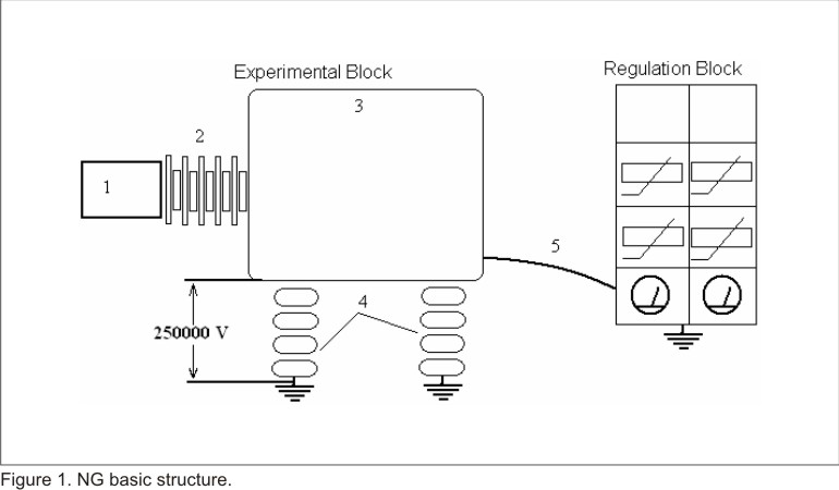
The experimental block contains several devices mainly located in the high voltage header 3, the acceleration tube 2 and the transport system 1.
Basic performance flows as follows, given the high vacuum ions are produced first and then electrostatically extracted from the ion source work volume, later on they are accelerated through 2 to finally impact over an adecuated target located in 1, where nuclear reaction generating neutrons takes place. The high voltage header 3 rests on porcelain isolators 4 and is usually polarized at 250 kV. At such a voltage a flux of 1012 neutrons / sec, with a mean energy of 14 MeV is generated.
The regulation block performs both the regulation and the monitoring of NG exploitation parameters which define its functioning. Such parameters are: Focusing Voltage and Current, Extracting Voltage and Current, Magnet Current, Gas Filter Current, Discharge Current. Both blocks are linked by a device consisting of two black boxes, one on each end and an optic chanel 5 through wich the information exchange flows. At present such a device is out of work and the possibilities of repairing it are not real.
Present research was aimed to design and construct an intelligent interface tailored to the investigation activity needs so as to have the communication between the generator blocks reestablished, the exploitation parameter´s reading automated and the information visualization through a pc-user interface, available.
Theoretic methods were used
· Documentation revision: Confirmed the extended usage of microcontrollers in the interface design and suggested some features like the USB communication to be available. There was also verified the application of infrared and radiofrecuency links when the electrical isolation is required. In our case the link through an optic fiber was choosen based on practical reasons.
· Systematization method: Leaded to the accumulation of theoretical and practical experiences on basic skills related to data acquisition devices design and communication between them and computer.
· Simulation method: Allowed to verify the used in the interface firmware efficacy.
· Empiric method: Aimed to obtain numeric information from the parameters reading in order to refine designs and to adjust the pc-user interface according to researcher needs.
The problem to be solved was that the device in charge of communicating the experimental and regulation blocks from the NG is out of order with no possibilities of repairing. So the design and construction of an intelligent interface to allow the automated reading of accelerator‘s exploitation parameters from a PC became the main research objective. Interface must be designed according to the following requirements:
· Electric isolation between the ends of the communication channel must be kept since they work at a voltage difference of 250 kV.
· An appropriate microcontroller performs the acquisition, conversion and data exchange given the request from a PC.
· The communication acquisition card-PC should be established through the USB bus since for such a purpose it is being widely extended [2].
· PC-user interface must be user friendly, flexible and powerful what can be guarantee by LabVIEW environment. So its design must be performed using LabVIEW.
· Design must consider the interface usage for further applications.
Several solutions related to communication electric isolation were studied, among them the use of a radiofrequency link between blocks, also their communication through an infrared path. Finally the optic fiber and its transceivers availability decided the choice.
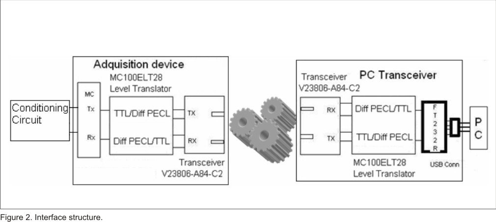
The simplest interface structure representation can be observed in the figure 2 presented below.
As it can be observed both interface ends are showed, the acquisition one sits in the experimental block, there is a microcontroller (MC) responsible for the data acquisition, analogue to digital conversion and further data sending to the computer. Before being transmitted (TX) through the optical fibre, which is represented by gears, signals from the controller must be translated both from TTL to differential PECL and then from electric to optic pattern. First translation comes from the transceiver requirements for incoming signals to fit the differential PECL standard and is accomplished by MC100ELT28 logic level translator [3], second, from the optic media through which data are sent. The data transmission and reception is performed by the compact transceiver V23806-A84-V2 [4], specially designed to handle optic signals.
At the computer side a double translation is also needed during reception (RX), it means that coming from optical fibre pulses are first translated from optical to electric pattern by the transceiver and after that accommodated from differential PECL to TTL logic so as to have an understandable data given to the computer.
Since USB signals are bidirectional [5] it becomes difficult to implement them through an optic channel, on the other hand the launching of USB 3.0 capable of handling optic signals has been recently announced by INTEL [6] but it is not yet available. That is why, an alternative to pure USB bus had to be introduced in the design, it was made through the application of a semiconductor piece named FT232R [7], also called bridge. It gives the possibility of synthesize a USB to serial RS232 converter; serial unidirectional signals are well supported and handled by optic transceivers.
Figure 3, showed below pictures the acquisition card schematic. It supports the microcontroller PIC16F74 [8] from MICROCHIP [9]. The most relevant microcontroller specifications are the availability of:
- 33 input/output configurable pins organized in four ports B, C, D and AN0-AN7.
- An 8 bit ADC with up to 8 multiplexed channels.
- A USART for serial communication.
- Three timers with several working modes.
- 4K program memory.
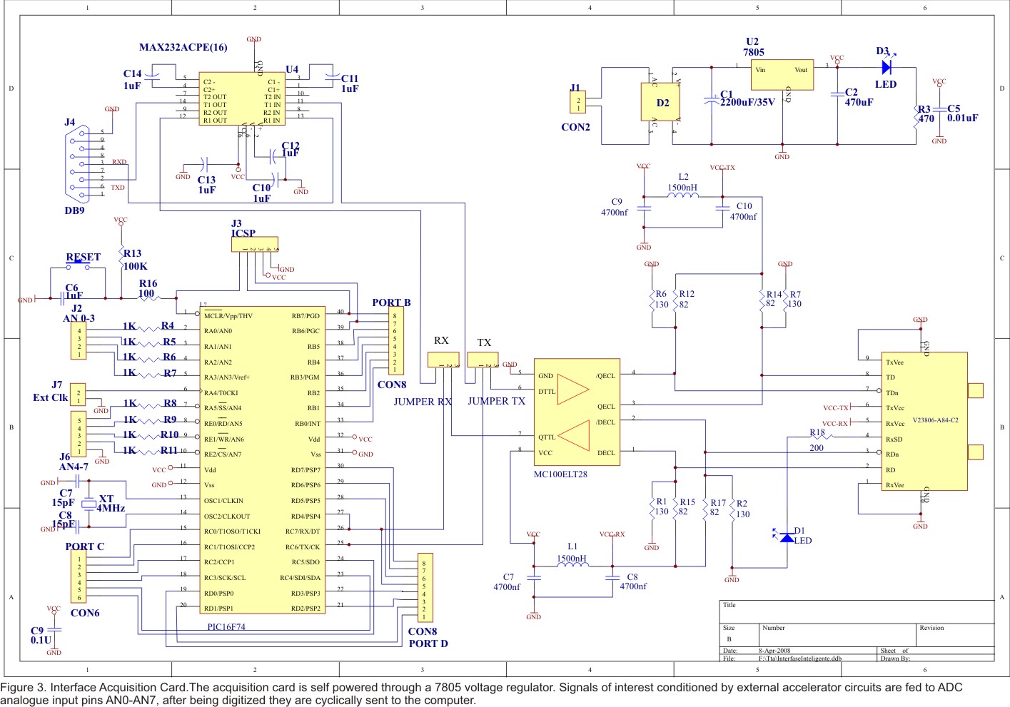
As can be seen all pins are accessible from implemented connectors as well as those dedicated to In Circuit Serial Programming (ICSP), a very useful facility during the development stage. Microcontroller runs on a 4 MHz quartz crystal, what can be increased up to 20 MHz.
Jumpers RX and TX allow the optional data output either directly to a computer through serial RS-232 driver (MAX232ACPE) [10] or through the optic channel going first through the logic level converter and transceiver.
The acquisition card is self powered through a 7805 voltage regulator. Signals of interest conditioned by external accelerator circuits are fed to ADC analogue input pins AN0-AN7, after being digitized they are cyclically sent to the computer.
The optical fibre transceiver circuit is also showed in figure 3, it performs the signal conversion from electric to optic pattern. If optical fibre media was chosen to send data, signals coming out from the microcontroller USART are converted to standard differential logic PECL by level converter MC100ELT28, then converted signals are fed to the optic transceiver which inject them to the optical fibre. Such a transceiver as V23806-A84-C2 from SIEMENS integrates the optic transmitter and receiver and performs the laser modulation and power control.
As soon as request signals from computer come from the optic channel, they are converted by the receiver into differential PECL compatible electrical pulses and converted again to TTL compatible signals, which are fed to the microcontroller serial USAR in order to be read.
Since such circuits are designed to work at very high rates and feature very high noise immunity and considering that in our case there is no requirement for a so high information exchange speed, there will be a reserve available for further developments.
Converting signals from electrical to optic pattern and vice versa is a requirement at both optical channel ends that is why, there is on the computer transceiver card a similar circuit performing such a function.
Figure 4, shows the schematic of this card, the new element here is the usage of FT 232R Bridge advantages. The FT232R is a USB to serial UART interface with optional clock generator output, and the new FTDIChip-ID™ security dongle feature. In addition, asynchronous and synchronous bit bang interface modes are available. USB to serial designs using the FT232R have been further simplified by fully integrating the external EEPROM, clock circuit and USB resistors onto the device.
As commented before, USB implementation through an optic channel was an objective hard to fulfil, a generous device like the FT232R allows the implementation of the communication from the computer through the USB port thus overcoming arisen design obstacles.
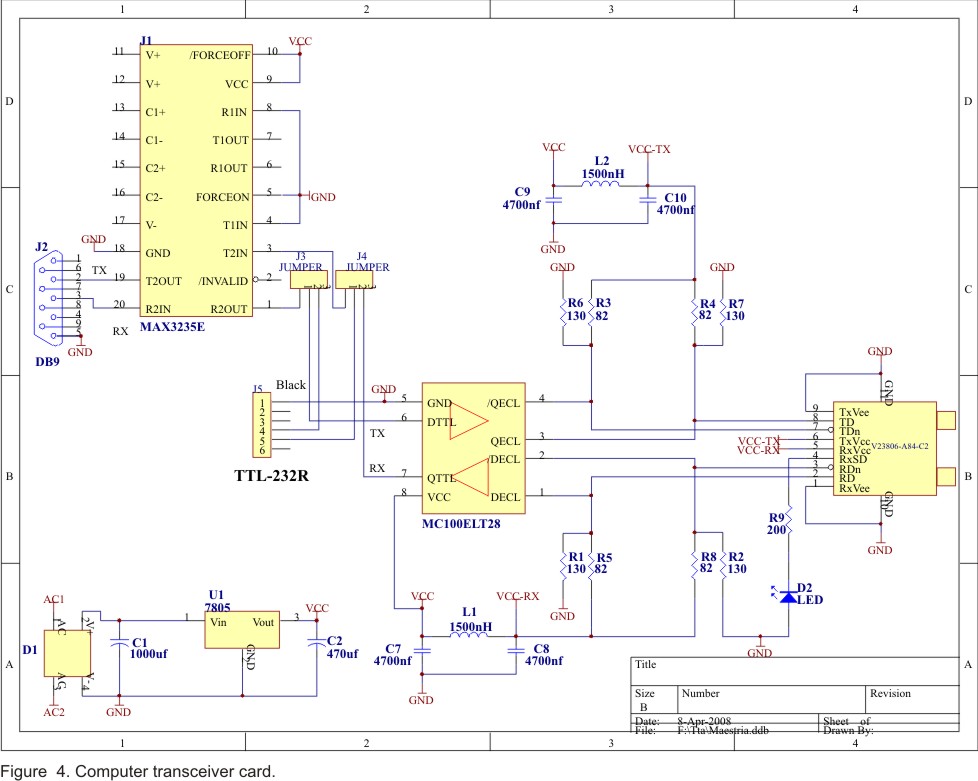
Present design uses the facilities of a USB to TTL Serial Cable [11], which contains in the plug itself the integrated circuit FT232R, so there is just the requirement of a 6 pin connector indicated as J5.
This card is also self powered and has the possibility of sending through the optical fibre signals coming either from serial RS232 port or from TTL_232R Bridge. By selecting the appropriate jumpers (J4, J5) position the option needed can be set.
The 5 V voltage regulator 7805 sources power to the optical transceiver, it is well decoupled so as to guarantee a clean dc supply level. A MAX3235E [12] is an RS232 driver, guarantees serial communication and does not need for external capacitors what is also an advantage.
The PC-user interface is the window through which researcher accesses the information of interest. It was designed using Lab VIEW environment. The application front panel is showed in the next coming figure 5. Such an environment offers a wide range of possibilities to handle data, and gives always the chance of upgrading the application. Designing the interface with Lab VIEW allows a more friendly and efficient exploitation of the application.

Lab VIEW code works as follows: it sends from the computer to the microcontroller on the acquisition card the request to perform data reading. Readings might be performed either from a previously defined channel or following a cycle path, where every channel is cyclically read.
The front panel design considered the availability of time and date and also shows either if a specific channel is being continuously accessed or if all together are being read one after another, left standing leds will show so by turning on.
A communication checking in order to test whether information exchange is supported or not is also available, Com OK led will be turned on in case everything is ok and off in the opposite case. These options may be selected through the Lectura box
]]> Obtained data are visualized both through analogue and digital indicators. Different colours are useful to differentiate one channel from another. Development stage of the interface is still not finished, that is why more options and resources are expected to be added over.Now, few words on the C code running on the PIC controller, it just takes the information request sent by the PC and performs the channel selection, data reading, digital conversion and sends back to the computer the acquired information. There should be added that any data acquisition is performed once the previous conversion has been completed.
RESULTS
The communication reestablishment between NG blocks,through an intelligent interface.
· Automated the NG exploitation parameter´s data acquisition.
· Upgraded the original NG interface.
· The computer usage introduction in the generator exploitation process.
· The inmediate availability of computational tools for the NG management.
· The creation of initial conditions for further automation of other NG systems.
· The availability of a selfsufficient acquisition card which applicaction could be extended both to different experiments and to upgrade and refurbish old equipments.
An important experience on the data acquisition device design under severe requirements has been gained. The obtained interface is suitable to be applied either as electrically isolated data acquisition device or as a simple data acquisition card, capable of acquiring up to 8 analogue signals.
Obtained results also include the introduction of a computer and the computational resources in the NG exploitation, what turns into a new NG feature and allows its further upgrade.
DISCUSSION
A number of works are being carried out in order to upgrade our accelerator; they are related to physic and also electronic profiles. In this context having no link between accelerator’s blocks was a real challenge to overcome. The intelligent interface brought the communication solution and also many other advantages easing further upgrading works on the NG.
Measurements performed by the acquisition card were verified through their comparison with other measuring tool as digital voltmeter. Obtained readings from the interface and from the digital voltmeter showed along the whole measuring range a small difference between each other, more precisely at the level of the less significant cipher. Difference can be explained through the ADC resolution. It is well known that a digital voltmeter is a specially designed measuring device and features a more powerful ADC what means a higher resolution, thus giving a more consistent reading. In the case of PIC16F74 the ADC allows conversion of an analogue input signal to a corresponding 8-bit digital number. Obtained results adequately fulfil the application expectative and give faithful enough information on the monitored magnitudes.
There are still not used microcontroller resources useful to take advantage and extend present work to other installation systems as for example the dedicated to high vacuum. Another example is that from previous development works [13] on the NG an ion source excited by a Radio-Frequency (RF) Field was obtained, now the RF generator located in the high voltage header and responsible for the RF field must be controlled trough the optical intelligent interface.
Having signals readings on the computer side gives the advantage of closing the control loop, what is indispensable for automation and control. It means that once a sample of controlled magnitude is available it is possible to keep it unchanged through a control loop or to appropriately adjust it as needed, we already have sampled signal of interest and visualize them through the computer – user interface, now the control loop must be close by sending back to the high voltage header microcontroller the adequate command.
At CEADEN there are previous experiences in the design of development platforms [14] but designs using optical fibre as transmission media were no carried out, so this comes to be first step in this direction. Data acquisition is a very common exercise today and the card implemented for this purpose is self-sufficient to be extended to other experimental applications so as to have experiment monitored from a computer.
Results of this experience were presented in the «First Latin American Workshop on Distributed Laboratory Instrumentation Systems in Physics» held in Valdivia, Chile, at the Austral University of Chile from January7th to February 4th, 2008.
]]> REFERENCES[1] IAEA. Manual for troubleshooting and upgrading of neutron generators. IAEA-TECDOC-913. 1996.
[2] MAXIM. Application Note 3637: Add USB to Anything. Maxim Integrated Products, Dallas Semiconductor. 2005. [en línea]. Disponible en: URL:http://www.maxim-ic.com/an3637.Consultado: 2007.
[3]On Semiconductor. Data Sheet, MC10ELT28, MC100ELT28: 5 V_TTL to Differential PECL and Differential PECL to TTL Translator. Semiconductor Components Industries. 2006. [en línea]. Disponible en: URL:http://www.onsemi.com/pub_link/Collateral/MC10ELT28-D.PDF Consultado: 2007.
[4] INFINEON TECHNOLOGIES. Data Sheet, V23806-A34-C2: Single Mode FDDI 1x9 Transceiver with SC Receptacle. Infineon Technologies AG. 2000. [en línea]. Disponible en: URL:http://www.datasheetcatalog.net/es/datasheets_pdf/V/2/3/8/V23806-A84-C2.shtml. Consultado: 2007.
[5] Maxim. Application Note 1822: USB on the go Basics. Maxim Integrated Products, Dallas Semiconductor. 2002. [en línea]. Disponible en: URL:http://www.maxim-ic/an1822
Consultado:2007.
[6] HRUSKA J. Intel announces, demosntrates USB 3.0. Ars Technica, the art of technology . Sep 18, 2007. [en línea]. Disponible en: URL:http://arstechnica.com/news.ars/post/20070918-intel-announces-demonstrates-usb-3-0.html.
[7] Future Technology Devices International Ltd.. Data Sheet, FT232R: FT232R USB UART I.C. 2005. [en línea]. Disponible en:
URL:http://www.ftdichip.com/Documents/DataSheets/DS_FT232R.pdf Consultado: 2008. ]]>
[8] Microchip Technology Inc.. DataSheet, PIC16F7X: 28/40-pin, 8-bit CMOS FLASH Microcontrollers. 2002. [en línea]. Disponible en: URL:http://www.robotstore.com/download/246781.pdf.
[9] Microchip Technology Inc.. A Leading Provider of Microchip & Analog Semioconductors.
[en línea]. Disponible en: URL:http://www.microchip.com/stellent/idcplg?IdcService=SS_GET_PAGE&nodeId=64
Consultado: 2006.
[10] TEXAS INSTRUMENTS INC.. Data Sheet, MAX232: Dual EIA-232 DRIVERS/RECEIVERS. March 2004. [en línea]. Disponible en:
URL:http://rocky.digikey.com/WebLib/Texas%20Instruments/Web%20data/MAX232,232I.pdf Consultado: 2007.
[11] Future Technology Devices International Ltd. FTD232R Modules, TTL-232R USB – TTL Level Serial Converter. 2007. [en línea]. Disponible en: URL:http://www.ftdichip.com/ttl232r.htm Consultado: 2008.
[12] Maxim Integrated Products. Data Sheet: ±15kV ESD-Protected, 1ìA, 250kbps, 3.3V/5V, Dual RS-232 Transceivers with Internal Capacitors. 2000. [en línea]. Disponible en:
URL:www.ortodoxism.ro/datasheets/maxim/MAX3233E-MAX3235E.pdf.
[13] LEDO L. M.:Sistema de Radiofrecuencia para excitar una fuente de iones. Revista Nucleus, No. 39. 2006. ISSN 0864-084X. ]]>
[14] HERNÁNDEZ L., GONZÁLEZ Y, LÓPEZ N, ARTECHE R, MARTÍN J L. Proceedings of the 1st International Symposium for Computation and Electronics INFORMATICA’ 2005. ISBN: 959-7164-87-6.
Recibido: 4 de marzo de 2008
Aceptado: 26 de marzo de 2008
ledo@ceaden.edu.cu
]]>