<?xml version="1.0" encoding="ISO-8859-1"?><article xmlns:mml="http://www.w3.org/1998/Math/MathML" xmlns:xlink="http://www.w3.org/1999/xlink" xmlns:xsi="http://www.w3.org/2001/XMLSchema-instance">
<front>
<journal-meta>
<journal-id>1815-5944</journal-id>
<journal-title><![CDATA[Ingeniería Mecánica]]></journal-title>
<abbrev-journal-title><![CDATA[Ingeniería Mecánica]]></abbrev-journal-title>
<issn>1815-5944</issn>
<publisher>
<publisher-name><![CDATA[Facultad de Ingeniería Mecánica. Instituto Superior Politécnico "José Antonio Echeverría"]]></publisher-name>
</publisher>
</journal-meta>
<article-meta>
<article-id>S1815-59442012000300008</article-id>
<title-group>
<article-title xml:lang="en"><![CDATA[Thermal and friction drop characteristic of heat exchangers with elliptical tubes and smooth fins]]></article-title>
<article-title xml:lang="es"><![CDATA[Caracterización térmica e hidráulica de intercambiadores de calor con tubos elípticos y aletas lisas]]></article-title>
</title-group>
<contrib-group>
<contrib contrib-type="author">
<name>
<surname><![CDATA[Borrajo-Pérez]]></surname>
<given-names><![CDATA[Rubén]]></given-names>
</name>
<xref ref-type="aff" rid="A01"/>
</contrib>
<contrib contrib-type="author">
<name>
<surname><![CDATA[Ititzo Yanagihara]]></surname>
<given-names><![CDATA[Jurandir]]></given-names>
</name>
<xref ref-type="aff" rid="A02"/>
</contrib>
<contrib contrib-type="author">
<name>
<surname><![CDATA[González-Bayón]]></surname>
<given-names><![CDATA[Juan José]]></given-names>
</name>
<xref ref-type="aff" rid="A01"/>
</contrib>
</contrib-group>
<aff id="A01">
<institution><![CDATA[,Instituto Superior Politécnico José Antonio Echeverría Centro de Estudio de Tecnologías Energéticas Renovables ]]></institution>
<addr-line><![CDATA[La Habana ]]></addr-line>
<country>Cuba</country>
</aff>
<aff id="A02">
<institution><![CDATA[,University of São Paulo Department of Mechanical Engineering ]]></institution>
<addr-line><![CDATA[São Paulo ]]></addr-line>
<country>Brazil</country>
</aff>
<pub-date pub-type="pub">
<day>00</day>
<month>12</month>
<year>2012</year>
</pub-date>
<pub-date pub-type="epub">
<day>00</day>
<month>12</month>
<year>2012</year>
</pub-date>
<volume>15</volume>
<numero>3</numero>
<fpage>243</fpage>
<lpage>253</lpage>
<copyright-statement/>
<copyright-year/>
<self-uri xlink:href="http://scielo.sld.cu/scielo.php?script=sci_arttext&amp;pid=S1815-59442012000300008&amp;lng=en&amp;nrm=iso"></self-uri><self-uri xlink:href="http://scielo.sld.cu/scielo.php?script=sci_abstract&amp;pid=S1815-59442012000300008&amp;lng=en&amp;nrm=iso"></self-uri><self-uri xlink:href="http://scielo.sld.cu/scielo.php?script=sci_pdf&amp;pid=S1815-59442012000300008&amp;lng=en&amp;nrm=iso"></self-uri><abstract abstract-type="short" xml:lang="en"><p><![CDATA[Pressure drop and heat transfer are the most important parameters in compact heat exchanger. There is a lack of information in the literature about heat exchanger with elliptical tube. The objective of this work was the experimental characterization of compact heat exchangers models using elliptical tube with eccentricity of 0,5 and smooth fins. The Reynolds numbers and the spacing were varied and always inside laminar regime. The experiments were conducted in an open wind tunnel using sublimation of naphthalene and the heat and mass transfer analogy. As results, the average and local Nusselt number and friction factor for 36 models were obtained. Correlations for Colburn and friction factors were presented. This correlations were obtained for 200<Re<1500 and isothermal fins. These are the first correlations presented in the open literature covering a wider range of pitches. A baseline for future implementations of enhancement heat transfer techniques is presented.]]></p></abstract>
<abstract abstract-type="short" xml:lang="es"><p><![CDATA[Caída de presión y transferencia de calor son importantes parámetros en intercambiadores de calor. Existe falta de información cuando de intercambiadores de calor y tubos elípticos se trata. El objetivo del trabajo fue caracterizar experimentalmente modelos de intercambiadores de calor con tubos elípticos y aletas lisas. El numero de Reynolds y los espaciamientos fueron variados, dentro del régimen laminar. Los experimentos fueron desarrollados en un túnel de viento de circuito abierto usando la sublimación de naftaleno y la analogía calor y masa. Los números de Nusselt medio, locales y el factor de fricción fueron obtenidos en forma de correlaciones de Factores de Fricción y Colburn. Las correlaciones, validas para 200<Re<1500 y aleta isotérmica. Son las primeras correlaciones que se aplican a un tan amplio rango de espaciamientos. Se presenta una línea base para futura comparación en la implementación de técnicas de intensificación de transferencia.]]></p></abstract>
<kwd-group>
<kwd lng="en"><![CDATA[friction factor]]></kwd>
<kwd lng="en"><![CDATA[heat transfer coefficient]]></kwd>
<kwd lng="en"><![CDATA[elliptical tube]]></kwd>
<kwd lng="en"><![CDATA[compact heat exchanger]]></kwd>
<kwd lng="es"><![CDATA[factor de fricción]]></kwd>
<kwd lng="es"><![CDATA[coeficiente de transferencia de calor]]></kwd>
<kwd lng="es"><![CDATA[tubos elípticos]]></kwd>
<kwd lng="es"><![CDATA[intercambiadores de calor compactos]]></kwd>
</kwd-group>
</article-meta>
</front><body><![CDATA[ <div align="right">    <P><font size="2" face="Verdana"><b>ART&Iacute;CULO ORIGINAL</b></font></P>    <P>&nbsp;</P></div>    <P><font size="4" face="Verdana"><b>Thermal  and friction drop characteristic of heat exchangers with elliptical tubes and  smooth fins</b></font>     <P>&nbsp;     <P><font size="3" face="Verdana"><b>Caracterizaci&oacute;n  t&eacute;rmica e hidr&aacute;ulica de intercambiadores de calor con tubos el&iacute;pticos  y aletas lisas</b></font>     <P>&nbsp;     <P>&nbsp;     <P><font size="2" face="Verdana"><b>Rub&eacute;n  Borrajo-P&eacute;rez<sup>I</sup>, Jurandir Ititzo Yanagihara<sup>II</sup>, Juan  Jos&eacute; Gonz&aacute;lez-Bay&oacute;n<sup></sup><sup>I</sup></b> </font>     <P><font size="2" face="Verdana">I  Instituto Superior Polit&eacute;cnico Jos&eacute; Antonio Echeverr&iacute;a. Centro  de Estudio de Tecnolog&iacute;as Energ&eacute;ticas Renovables. La Habana. Cuba.      ]]></body>
<body><![CDATA[<br> II University of S&atilde;o Paulo. Department of Mechanical Engineering.  S&atilde;o Paulo, Brazil </font>     <P>&nbsp;     <P>&nbsp; <hr>     <P><font size="2" face="Verdana"><b>ABSTRACT</b></font>      <P><font size="2" face="Verdana">Pressure drop and heat transfer are the most  important parameters in compact heat exchanger. There is a lack of information  in the literature about heat exchanger with elliptical tube. The objective of  this work was the experimental characterization of compact heat exchangers models  using elliptical tube with eccentricity of 0,5 and smooth fins. The Reynolds numbers  and the spacing were varied and always inside laminar regime. The experiments  were conducted in an open wind tunnel using sublimation of naphthalene and the  heat and mass transfer analogy. As results, the average and local Nusselt number  and friction factor for 36 models were obtained. Correlations for Colburn and  friction factors were presented. This correlations were obtained for 200&lt;Re&lt;1500  and isothermal fins. These are the first correlations presented in the open literature  covering a wider range of pitches. A baseline for future implementations of enhancement  heat transfer techniques is presented. </font>     <P><font size="2" face="Verdana"><b>Key  words:</b> friction factor, heat transfer coefficient, elliptical tube, compact  heat exchanger.</font> <hr>     <P><font size="2" face="Verdana"><b>RESUMEN</b></font>      <P><font size="2" face="Verdana">Ca&iacute;da de presi&oacute;n y transferencia  de calor son importantes par&aacute;metros en intercambiadores de calor. Existe  falta de informaci&oacute;n cuando de intercambiadores de calor y tubos el&iacute;pticos  se trata. El objetivo del trabajo fue caracterizar experimentalmente modelos de  intercambiadores de calor con tubos el&iacute;pticos y aletas lisas. El numero  de Reynolds y los espaciamientos fueron variados, dentro del r&eacute;gimen laminar.  Los experimentos fueron desarrollados en un t&uacute;nel de viento de circuito  abierto usando la sublimaci&oacute;n de naftaleno y la analog&iacute;a calor y  masa. Los n&uacute;meros de Nusselt medio, locales y el factor de fricci&oacute;n  fueron obtenidos en forma de correlaciones de Factores de Fricci&oacute;n y Colburn.  Las correlaciones, validas para 200&lt;Re&lt;1500 y aleta isot&eacute;rmica. Son  las primeras correlaciones que se aplican a un tan amplio rango de espaciamientos.  Se presenta una l&iacute;nea base para futura comparaci&oacute;n en la implementaci&oacute;n  de t&eacute;cnicas de intensificaci&oacute;n de transferencia. </font>     <P><font size="2" face="Verdana"><b>Palabras  claves:</b> factor de fricci&oacute;n, coeficiente de transferencia de calor,  tubos el&iacute;pticos, intercambiadores de calor compactos.</font> <hr>     <P>&nbsp;     ]]></body>
<body><![CDATA[<P>&nbsp;      <P><font face="Verdana" size="3"><b>INTRODUCTION</b></font>     <P>&nbsp;     <P><font size="2" face="Verdana">Many  process involving gas-to-gas or liquid-to-gas heat transfer, with low values of  heat transfer coefficients at the gas side, require the determination of the overall  heat transfer coefficient with high accuracy. In general, correlations for heat  exchangers are very useful for designers but usually these are restricted to a  few geometries and arrangements. </font>     <P><font size="2" face="Verdana">Correlations  for plate fin compact heat exchanger with staggered round tubes were developed  by McQuiston and Gray &amp; Webb apud Webb [1], thelatter being more accurate.  These correlations are valid for the following ranges: 2,55&#8805;<i>S<sub>T</sub>/d<sub>0</sub></i>&#8805;1,97;  2,58&#8805;<i>S<sub>L</sub>/d<sub>0</sub></i>&#8805;1,7 and 500&lt;<i>Re</i>&lt;24700.  Madi <i>et al</i> [2] carried out and experimental study where 28 heat exchangers  samples with plain and corrugated fins were tested. They presented correlations  for the prediction of Colburn factor <i>j </i>and the <i>f</i> factor with higher  accuracy than earlier correlations, being valid for a larger range of the geometrical  parameters. The elliptical tube geometry is one of the most studied non circular  arrangement, however, the information about these is not complete because of the  large number of parameters affecting the performance of the heat exchanger using  this geometry. Brauer apud Webb [1] and M. P. Ximenes in its PhD thesis in 1981  developed in Sao Jose dos Campos Brazil, were the first to study this kind of  geometry, comparing its performance to the round one. Bordalo &amp; Saboya[3]  focused their work in the hydraulic performance of heat exchangers with one and  two rows of tubes using a plain finned elliptical tube with the same pitches than  those tested by Ximenes in 1981. </font>     <P><font size="2" face="Verdana">Sohal  and O'Brien [4] carry out and numerical and experimental work where circular and  oval tubes were investigated and, among others results, they presented the local  and average heat transfer coefficients for one finned tube having smooth fin surface.  Burkova et al. [5], made a wide study for oval tubes in staggered distribution  and looking for the influence of the rows number. It was conducted following the  classical method of complete simulation and the Reynolds numbers employed were  in turbulent regime of flow. </font>     <P><font size="2" face="Verdana">Enhancement  heat transfer is a mean for save energy and materials. Vortex generators (VG),  among others techniques, has been occupying an important space in this field.  Jacobi and Joardar [6] obtained heat transfer enhancement up to 44 % with lower  pressure penalty for compact heat exchangers using in air-cooling and refrigeration  applications. A group of parameters related with vortex generators are being investigated,  length, height and angle of attack. M. Zeng [7] et all have developed a numerical  study of the influence of these parameters, optimized by Taguchi method, on the  hydrodynamics and heat transfer characteristic. Two optimal configurations were  obtained. During investigations in this area, different approach have been applied.  Digital particle image velocimetry (DPIV) as visualization technique was used  by Unal &amp; Atlar [8] to investigate the flow pattern on the near-wake of a  circular cylinder. The effect of vortex generators on this area was demonstrated.  </font>     <P><font size="2" face="Verdana">The VG have been used not only in heat  exchangers but also in channel [9] combined to wedge ribs. The Nusselt number  and friction factor values obtained from combined the ribs and the WVGs are found  to be much higher than those from the ribs or vortex generators used alone. </font>      <P><font size="2" face="Verdana">In other work, Lei et al [10] VG were used in  a finned circular tube with two rows. The authors found the j-factor to increase  by 35.1-45.2 % with a corresponding increase of 19.3-34.5 % in the friction factor.  The better location of VG were not coincident with previously consulted results  [11]. Drag reduction was a target of another work [12] where VG where used combined  to a bluf-body and significant reduction of pressure drop was obtained. </font>      <P><font size="2" face="Verdana">The small number of correlations for non circular  arrangement and their narrow scope of validity are the most important limitations  found in the bibliography at present. The increasing number of papers dealing  with tubes with non circular geometry is an indicative of the importance of this  subject. The improvement of thermo-hydraulic performance of compact heat exchanger  with finned tube is necessary because of economical and environmental constraints.  One way to reach this objective is to use tubes with better hydrodynamic performance  and a smaller wake region. </font>     ]]></body>
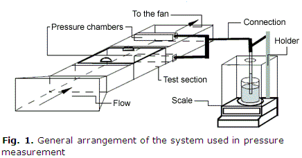
<body><![CDATA[<P><font size="2" face="Verdana">The present  work is an experimental study of the thermal and friction performance of scaled  models of plate fin heat exchanger with one and two rows of elliptical tubes.  The analogy between the heat and mass transfer was used for the average and local  Nusselt number determination. The friction factor was evaluated using a weighted  method by means of a digital balance. The objective of this work is to obtain  the average Nusselt number (<i>Nu</i>) and the friction factor (<i>f</i>) as function  of the Reynolds number in laminar regime for 36 heat exchanger models having one  or two rows of tubes where the transversal and longitudinal pitches were systematically  varied. </font>     <P><font size="2" face="Verdana">The importance of this study  lays in the necessity of make a good prediction of heat transfer and pressure  drop behavior for heat exchangers with finned elliptical tube in the stage design.  Additionally, the smooth characterization of this heat exchanger will be useful  in future investigations as a baseline to calculate the effect of any enhancement  technique applied. </font>     <P>&nbsp;     <P><font size="3" face="Verdana"><b>MATERIALS AND  METHODS</b></font>     <P>&nbsp;     <P><font size="2" face="Verdana">The experiments were conducted  in an instrumented open circuit wind tunnel consisting of a contraction at the  inlet, a test section, a centrifugal fan and a discharge tube. A flow straightener  was located before the test section to guarantee uniformity in the velocity profile  at model front. </font>     <P><font size="2" face="Verdana">The test section was  build in such a way to permit a rapid and easy access to the model. The wind tunnel  should be open circuit when naphthalene sublimation technique is used. A thermometer  with a resolution of 0,1 &ordm;C was placed in the rear part of tunnel to measure  the temperature of the air flow. The flow rate was measured by means of a vortex  flow meter with 1 % of uncertainty. Finally, an electronic balance of high resolution  having an RS-232 was used to weight the test specimen before and after each experimental  run. A chronometer was used for measuring time. </font>     <P><font size="2" face="Verdana">The  pressure measurement was carried out by developing a novel weighting method. It  consists of a tube with a pressure tap at one end and the other end submersed  in a beaker containing oil. The beaker is placed on the plate of the scale. The  general arrangement of the system is shown in the <a href="#f1">figure 1</a>.  The pressure difference, due to the flow losses, produces the elevation of the  liquid inside the tube, making lower the scale reading. The relation between this  reading and the pressure difference is called the manometer constant and can be  obtained manipulating the equations of hydrostatic [13]. </font>     <P align="center"><a name="f1"></a><img src="/img/revistas/im/v15n3/f0108312.gif" width="436" height="228" alt="Fig. 1. General arrangement of the system used in pressure measurement">      
<P>     ]]></body>
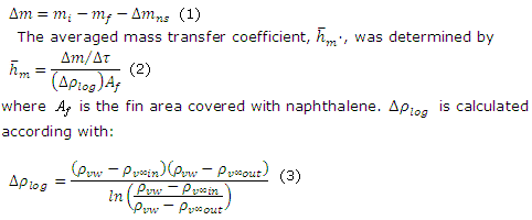
<body><![CDATA[<P><font size="2" face="Verdana">Each set of measurement was processed beginning  with the calculation of the mass transferred during the test (<i>&#916;m</i>),  obtained by the difference between the initial and the final weight of the specimen  (<i>m<sub>i</sub></i> and <i>m<sub>f</sub></i>) and considering also the mass  lost by natural sublimation <i>&#916;m<sub>ns</sub></i>: </font>     <P><font size="2" face="Verdana"><img src="/img/revistas/im/v15n3/e0108312.gif" width="482" height="200" alt="Equations 1, 2, and 3"></font>      
<P><font size="2" face="Verdana">where the density of vapor at the fin surface  level (<i>&#961;<sub>vw</sub></i>) is calculate using the ideal gas law at the  surface temperature. The vapor pressure of naphthalene is obtained by means of  Ambrose's correlation. The vapor density of the mainstream <img src="/img/revistas/im/v15n3/ero08312.gif" width="62" height="20" align="absmiddle">  at the exit of the channel was calculated using the <a href="#e4">equation 4</a>.  <img src="/img/revistas/im/v15n3/eri08312.gif" width="45" height="21" align="absmiddle">  is considered null because the wind tunnel is open circuit. </font>     
<P><font size="2" face="Verdana"><a name="e4"></a><img src="/img/revistas/im/v15n3/e0408312.gif" width="120" height="39" align="absmiddle" alt="Equation 4">(4)</font>      
<P>     <P><font size="2" face="Verdana">The denominator of <a href="#e4">equation  4</a> is the volumetric air flow rate in the channel, between two consecutive  fins. Therefore, the mass Stanton number could be determined by the <a href="#e5">equation  5</a>: </font>     <P><font size="2" face="Verdana"><a name="e5"></a><img src="/img/revistas/im/v15n3/e0508312.gif" width="78" height="41" alt="Equation 5" align="absmiddle">  (5) </font>     
<P><font size="2" face="Verdana">where u is the average velocity in  the minimum free flow area of the channel. From the analogy between the heat and  mass transfer we could write: </font>     <P><font size="2" face="Verdana"><img src="/img/revistas/im/v15n3/e0608312.gif" width="124" height="45" align="absmiddle" alt="Equation 6">  (6) </font>     
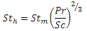
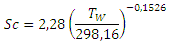
<P><font size="2" face="Verdana">where <i>St<aub>h</aub></i><aub></aub>  is the heat transfer Stanton number and <i>S<sub>c</sub></i> is the Schmitd number,  obtained from Cho's correlation as function of the temperature of the wall, <i>T<sub>w</sub></i>.  </font>     ]]></body>
<body><![CDATA[<P><font size="2" face="Verdana"><a name="e7"></a><img src="/img/revistas/im/v15n3/e0708312.gif" width="171" height="46" align="absmiddle" alt="Equation 7">  (7) </font>     
<P><font size="2" face="Verdana">The Reynolds number was calculated  using the definition of hydraulic diameter [13]. The Nusselt number was calculated  by the <a href="#e8">equation 8</a>. </font>     <P><font size="2" face="Verdana"><a name="e8"></a><img src="/img/revistas/im/v15n3/e0808312.gif" width="99" height="23" align="absmiddle" alt="Equation 8">  (8) </font>     
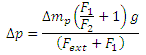
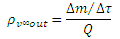
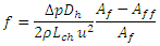
<P><font size="2" face="Verdana">The friction factor was calculated  by the <a href="#e9">equation 9</a>, where <i>&#916;p</i> is the pressure drop  produced by the model, <i>p</i> is the air density and L<sub>ch</sub> the channel  length. An area correction was used to normalize the friction factor. </font>      <P><font size="2" face="Verdana"><a name="e9"></a><img src="/img/revistas/im/v15n3/e0908312.gif" width="147" height="43" alt="Equation 9" align="absmiddle">  (9) </font>     
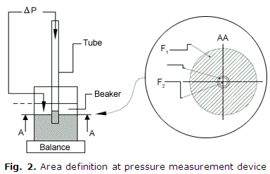
<P><font size="2" face="Verdana">where <i>A<sub>ff</sub></i> is the  frontal fin area of model and <i>A<sub>f</sub></i> is the frontal area of model.  The pressure drop through the model is obtained by the following manometer equation.  Where <i>&#916;m<sub>p</sub></i> is the scale reading,<i> g</i> is the acceleration  of the gravity and the rest are areas defined in the <a href="#f2">figure 2</a>.  </font>     <P><font size="2" face="Verdana"><img src="/img/revistas/im/v15n3/e1008312.gif" width="146" height="55" align="absmiddle" alt="Equation 10">  (10) </font>     
<P align="center"><a name="f2"></a><img src="/img/revistas/im/v15n3/f0208312.gif" width="384" height="248" alt="Fig. 2. Area definition at pressure measurement device">      
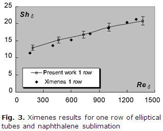
<P>     <P><font size="2" face="Verdana">The experimental technique and the procedure  used in this work were certified by comparison with experimental results available  in the literature. <a href="#f3">figure 3</a> presents the experimental results  by Ximenes and those obtained in the present work for the same transversal pitch.  The values were plot using the Sherwood number (<i>Sh</i>) to avoid the possible  divergence introduced by the exponent of the heat and mass transfer analogy and  the Schmidt number. </font>     ]]></body>
<body><![CDATA[<P align="center"><a name="f3"></a><img src="/img/revistas/im/v15n3/f0308312.jpg" width="319" height="256" alt="Fig. 3. Ximenes results for one row of elliptical tubes and naphthalene sublimation">      
<P><font size="2" face="Verdana">For the pressure drop, <a href="#f4">figure 4</a>  presents the loss coefficient K, calculated by Bordalo &amp; Saboya[3] for two  row of elliptical tubes and the same parameter for the present work (same longitudinal  and transversal pitches are considered). The agreement is good, with the differences  averaging 5,42 %. This value is lower than the experimental uncertainty. The Reynolds  number (<i>Re</i>) is based on the channel height and front velocity. In general,  the present results are in good agreement with previous works, although some deviations  can be noted at lower Reynolds number, in which the uncertainties is higher for  both referenced works. When both of figures (<a href="#f3">Fig. 3</a> &amp; <a href="#f4">Fig.  4</a>) are examinated can be said that the present results are matching with the  previous experiments if thermal and pressure drop are considered. </font>     <P align="center"><a name="f4"></a><img src="/img/revistas/im/v15n3/f0408312.jpg" width="319" height="242" alt="Fig. 4. Friction results of Bordalo &amp; Saboya[3] for one row of elliptical tubes">      
<P>     <P><font size="2" face="Verdana">The local Nusselt number was determined by  means of an evaporation technique based in the mass transfer analogy. It is based  in the change of color suffered by a surface, where wet chalk was previously spread,  and a dried process is established. This surface is used to substitute a portion  of the fin in a compact heat exchanger model and it is placed in the wind tunnel.  The air flowing throughout the heat exchanger passage produces the water evaporation  and subsequently the mentioned change of color. The difference in the color of  any point of the surface is obtained by computer manipulation of the bitmap file  resulting from successive black and white snap of the surface. A previous calibration  is made to obtain the local mass transfer-gray scale coef. (<i>C</i>): </font>      <P><font size="2" face="Verdana"><img src="/img/revistas/im/v15n3/e1108312.gif" width="88" height="57" align="absmiddle" alt="Equation 11">  (11) </font>     
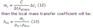
<P><font size="2" face="Verdana">where <i>m<sub>i</sub></i> and <i>c<sub>i</sub></i>  are the mass of water evaporated and the value of the gray scale change at a point  of the surface. <i>N </i>is the number of point defined over the surface. The  <a href="#e12">equation 12</a> calculates the local rate of mass transfer per  unit area, where <i>t</i> is the time elapsed between two consecutive snaps and  Aplaca is the surface area. </font>     <P><font size="2" face="Verdana"><a name="e12"></a><img src="/img/revistas/im/v15n3/e1208312.gif" width="324" height="97" alt="Equation 12 y 13" align="absmiddle"></font>  <font face="Verdana" size="2">(12) and (13)</font>     
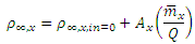
<P><font size="2" face="Verdana">where  the concentration at surface (<i>&#961;<sub>w</sub></i>) can be calculated by  the state equation. The concentration in the flow of air over the surface at the  coordinate <img src="/img/revistas/im/v15n3/ex08312.gif" width="51" height="20" align="absmiddle">  in agreement with the conservation equation, is given by the <a href="#e14">equation  14</a>, considering the area up to the coordinatex, (<i>A<sub>x</sub></i>), and  the flow concentration at entrance of the passage <img src="/img/revistas/im/v15n3/eal08312.gif" width="56" height="19" align="absmiddle">.  </font>     
<P><font size="2" face="Verdana"><a name="e14"></a><img src="/img/revistas/im/v15n3/e1408312.gif" width="179" height="41" alt="Equation 14" align="absmiddle">  (14) </font>     
]]></body>
<body><![CDATA[<P><font size="2" face="Verdana">where <img src="/img/revistas/im/v15n3/em08312.gif" width="29" height="22" align="absmiddle">  is calculated integrating on fin area. Additional information about the evaporation  technique can be found in the Phd thesis &quot;Experimental analysis of heat transfer  enhancement in compact heat exchangers with elliptical geometry using vortex generators&quot;  developed by the author in Sao Paulo University Brazil, 2001. </font>     
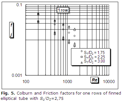
<P><font size="2" face="Verdana">The  uncertainty analysis was carried out and the results indicated an uncertainty  of 6 % for the average Nusselt number, 7 % for the local Nusselt number and 10  % for the friction factor, both uncertainties with 95 % of confidence level.</font>      <P>&nbsp;     <P><font size="2" face="Verdana"><font size="3"><b>RESULTS AND DISCUSSION</b></font></font>      <P>&nbsp;     <P><font size="2" face="Verdana"><a href="#f5">Figure 5</a> presents the experimental  results for models with one row. The figure presents a log-log plot of the Colburn  and friction factor for only three different S<sub>T</sub>/D<sub>2</sub> values;  the rest of S<sub>T</sub>/D<sub>2</sub> (2,00; 2,50; 2,75) is not presented to  avoid visual confusion in the graphics. </font>     <P align="center"><a name="f5"></a><img src="/img/revistas/im/v15n3/f0508312.jpg" width="394" height="328" alt="Fig. 5. Colburn and Friction factors for one rows of finned elliptical tube with SL/D2=2,75">      
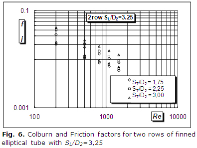
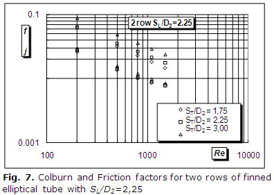
<P><font size="2" face="Verdana">The results of models having two rows of finned  elliptical tubes are presented in the <a href="#f6">figure 6</a> and <a href="#f7">figure  7</a> for the extreme <i>S<sub>L</sub>/D<sub>2</sub></i> values of 3,25 and 2,25  and to the same values of S<sub>T</sub>/D<sub>2</sub> already presented for one  row models.</font>     <P align="center"><a name="f6"></a><img src="/img/revistas/im/v15n3/f0608312.jpg" width="395" height="297" alt="Fig. 6. Colburn and Friction factors for two rows of finned elliptical tube with SL/D2=3,25">      
<P align="center"><a name="f7"></a><img src="/img/revistas/im/v15n3/f0708312.jpg" width="396" height="281" alt="Fig. 7. Colburn and Friction factors for two rows of finned elliptical tube with SL/D2=2,25 ">      
]]></body>
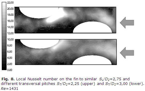
<body><![CDATA[<P><font size="2" face="Verdana">The observation of <a href="#f5">figure 5</a>  to <a href="#f7">figure 7</a> indicates the influence of the transversal and longitudinal  pitches and the number of rows on the thermal performance of heat exchanger models  with finned elliptical tubes. The increase of the dimensionless transversal pitch  produces an increment of the Colburn factor. </font>     <P><font size="2" face="Verdana">This  behavior happens due to higher values of the Nusselt number. This is possible  only if the heat transfer coefficient grows, because the hydraulic diameter decreases  as the transversal pitch is increased. This phenomenon could explain the small  sensitivity to heat transfer when S<sub>T</sub>/D<sub>2</sub> is augmented. Although  the tendency was similar for models with one or two rows, it was observed a larger  sensitivity in the first case. The increment in the average heat transfer coefficient  is possible when S<sub>T</sub>/D<sub>2</sub> is higher, because of the smaller  length of the models and the gradual reduction of wake region when the tube diameter  is reduced. This is more significant for one-row models, considering the higher  value of the mean heat transfer coefficient over the channel. It is also necessary  to consider the higher velocities present in the channel when Dh is lower for  the same Reynolds number. </font>     <P><font size="2" face="Verdana">The <a href="#f8">figure  8</a> shows the local Nusselt number distribution on the fin of two models with  the same longitudinal pitch and different transversal pitch. The arrows are indicating  the flow direction. The vortex system in the front of the second row tube is stronger  for the model with the smaller S<sub>T</sub>/D<sub>2</sub> because of larger diameter  of tube; however the bigger length of these models produces a lower average Nusselt  number. Is noted too a minor wake area for the models with smaller diameter.</font>      <P align="center"><a name="f8"></a><img src="/img/revistas/im/v15n3/f0808312.jpg" width="500" height="314" alt="Fig. 8. Local Nusselt number on the fin to similar SL/D2=2,75 and different transversal pitches ST/D2=2,25 (upper) and ST/D2=3,00 (lower). Re=1431 ">      
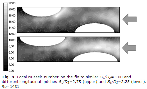
<P><font size="2" face="Verdana">Diminishing the longitudinal pitch has a positive  impact on the heat transfer behavior, producing an increment of the Nusselt number  by reducing the total fin length. In this case the hydraulic diameter grow when  the length is reduced. At the same time, the heat transfer coefficient increases  and both have a large influence on the variation of the Nusselt number with S<sub>L</sub>/D<sub>2</sub>.  The <a href="#f9">figure 9</a> is showing the local Nusselt number on the fins  of two models with the same adimensional transversal pitch and two values of the  longitudinal pitch. The model with the smaller adimensional longitudinal pitch  show a higher average Nusselt number, predominant clearer areas are noted in the  lower picture. Should be remembered that the length of these models is smaller  than presented in the upper picture. </font>     <P align="center"><a name="f9"></a><img src="/img/revistas/im/v15n3/f0908312.jpg" width="505" height="307" alt="Fig. 9. Local Nusselt number on the fin to similar ST/D2=3,00 and different longitudinal pitches SL/D2=2,75 (upper) and SL/D2=2,25 (lower). Re=1431 ">      
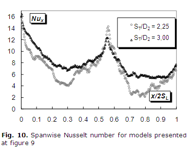
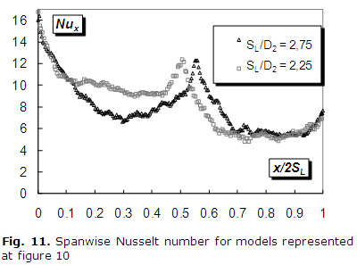
<P><font size="2" face="Verdana">The spanwise Nusselt number for the models compared  in the <a href="#f8">figure 8</a> and <a href="#f9">figure 9</a> are presented  in the <a href="#f10">figure 10</a> and <a href="#f11">figure 11</a>. Could be  observed the mentioned stronger peak of heat transfer in front of the second row  for the models with S<sub>T</sub>/D<sub>2</sub>=2,25 and the influence of the  developing thin layer for the models with the smaller lengths. </font>     <P align="center"><a name="f10"></a><img src="/img/revistas/im/v15n3/f1008312.jpg" width="388" height="304" alt="Fig. 10. Spanwise Nusselt number for models presented at figure 9">      
<P>&nbsp;     <P align="center"><a name="f11"></a><img src="/img/revistas/im/v15n3/f1108312.jpg" width="400" height="297" alt="Fig. 11. Spanwise Nusselt number for models represented at figure 10 ">      
]]></body>
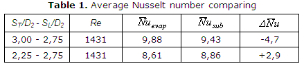
<body><![CDATA[<P><font size="2" face="Verdana">In <a href="#t1">table 1</a> are presented the  global Nusselt numbers obtained by both of techniques used in this work showing  the small deviation for the two models compared. </font>     <P align="center"><a name="t1"></a><img src="/img/revistas/im/v15n3/t0108312.gif" width="439" height="96" alt="Table 1. Average Nusselt number comparing">      
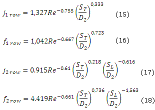
<P><font size="2" face="Verdana">The friction factor has the same behavior of  the Colburn factor as far as the pitch variation is concerned. When the transversal  pitch is augmented the friction factor f increases because the relation Dh/L also  increases and its effect is predominant over the friction factor, despite the  fact that the pressure drop diminishes with S<sub>T</sub>/D<sub>2</sub>. When  the influence of S<sub>L</sub>/D<sub>2</sub> is analyze, a reduction of the friction  factor is observed the increasing of longitudinal pitch. In this case, the diminishing  of the relation Dh/Ltroc is determinant despite the higher pressure drop caused  by larger fins. Finally the influence of the row number could be analyzed by comparison  of the <a href="#f5">figure 5</a> and <a href="#f7">figure 7</a> corresponding  to one and two rows models having the same transversal and longitudinal pitches.  It was noted an approximation between their behaviors for the highest Reynolds  numbers. On the other hand, the models with one row of tubes have a better thermal  performance when the velocities are low (note a more negative slope of <i>j</i>  vs Re plotted in <a href="#f5">Fig. 5</a> when compared to <a href="#f7">Fig.7</a>).  The growing importance of the vortical system and a minor contribution of the  boundary layer in the second row of models having two rows is the reason for the  improvement of the thermal performance when the velocity grows. The absence of  vortical system in one row model affects its performance at higher velocities.  </font>     <P><font size="2" face="Verdana">Using approximately six hundred experimental  values obtained in this work, correlations for friction and Colburn factor were  determined. The correlations, presented below, were obtained using the Mathcad  software and they are valid for 200&#8804;Re&#8804;1500; 1,75&#8804;S<sub>T</sub>/D<sub>2</sub>&#8804;3,00;  2,25&#8804;S<sub>L</sub>/D<sub>2</sub>&#8804;3,25 and isothermal fin. </font>      <P><font size="2" face="Verdana"><img src="/img/revistas/im/v15n3/e1508312.gif" width="310" height="220" alt="Equations 15-18"></font>      
<P><font size="2" face="Verdana"> </font>     <P>&nbsp;     <P><font size="2" face="Verdana"><font size="3"><b>CONCLUSIONS</b></font></font>      <P>&nbsp;     <P><font size="2" face="Verdana">The thermal and friction characterization  of thirty-six models (six with one row) of compact heat exchanger with finned  elliptical tubes was carried out. The effects resulting from variations of the  transversal and longitudinal pitches in a wide range were analyzed. The Nusselt  number was found increasing when the transversal pitch is augmented or the longitudinal  pitch is diminished and the causes of this behavior were analyzed. The horseshoe  vortex system generated in front of the tubes and the developing boundary layer  were the mechanisms responsible for the heat transfer enhancement. A novel technique  for pressure measurement was developed and certified during this work. The average  Nusselt number behavior was studied by measurement of local Nusselt numbers on  the fin. A group of simple empirical correlations were obtained considering the  influence of the Reynolds numbers the longitudinal and transversal pitches. These  correlations for compact heat exchangers with one and two rows of elliptical tubes,  considering smooth fin and isothermal condition, were never presented before.  A baseline to compare the performance of smooth configuration with enhanced configuration  is now available. </font>     ]]></body>
<body><![CDATA[<P>&nbsp;     <P><font size="2" face="Verdana"><font size="3"><b>REFERENCES</b></font></font>      <P>&nbsp;     <!-- ref --><P><font size="2" face="Verdana">1. Webb, R. L. <i>Principles of Enhanced  Heat Transfer</i>. 1st ed. New York: John Wiley &amp; Sons. 1994. 452 p. ISBN  10 0471577782.     </font>     <!-- ref --><P><font size="2" face="Verdana">2. Madi, M., Jonhs, R.  y Heikal, M. &quot;Performance Characteristics Correlation for Round Tube and  Plate Finned Heat Exchangers&quot;. <i>International Journal of Refrigeration</i>.  1998, vol. 21, n&#186; 7. p. 507-517. ISSN 0140-7007.     </font>     <!-- ref --><P><font size="2" face="Verdana">3.  Bordalo, S. and Saboya, F. E. &quot;Pressure Drop Coefficient for Elliptical and  Circular Sections in One, Two and Three-row Arrangements of Plate Fin and Tube  Heat Exchangers&quot;. <i>Journal of the Brazilian Society of Mechanical Science</i>.  1999. vol. 21, n&#186;. 4. p. 600-610. ISSN 1678-5878.     </font>     <!-- ref --><P><font size="2" face="Verdana">4.  Sohal, M. S. and O'Brien, J. E. &quot;Improving Air-Cooled Condenser Performance  Using Winglets and Oval Tubes in a Geothermal Power Plant&quot;. <i>Geothermal  Resources Council Transactions</i>. 2001. vol. 25. p. 234-238. ISSN 0193-5933.      </font>     <!-- ref --><P><font size="2" face="Verdana">5. Burkova, V. K., Medvedskiia, V. P.,  Kochegarovaa, I. Y. <i>et al</i>. &quot;Studies of Heat Transfer and Aerodynamics  in Bundles Assembled from Oval Tubes&quot;. <i>Thermal Engineering</i>. 2010.  vol. 57, n&#186; 3. p. 227-231. ISSN 0040-6015.     </font>     <!-- ref --><P><font size="2" face="Verdana">6.  Joardar1, A. and Jacobi, A. M. &quot;Heat transfer enhancement by winglet-type  vortex generator arrays in compact plain-fin-and-tube heat exchangers&quot;. <i>International  Journal of Refrigeration</i>. 2008. vol 31. p. 89-97. [Consulted in april 16 of  2012], Available in: <a href="http://www.elsevier.com/locate/ijrefrig" target="_blank">http://www.elsevier.com/locate/ijrefrig</a>.  ISSN 0140-7007.     </font>     <!-- ref --><P><font size="2" face="Verdana">7. Zeng, M., Tang, L.  H., Lina, M. <i>et al</i>. &quot;Optimization of heat exchangers with vortex-generator  fin by Taguchi Method&quot;. <i>Applied Thermal Engineering</i>. 2010. vol. 30.  p.1775-1783. [Consulted in april 20 of 2012], Available in: <a href="http://www.elsevier.com/locate/apthermeng" target="_blank">http://www.elsevier.com/locate/apthermeng</a>.  ISSN 1359-4311.     </font>     <!-- ref --><P><font size="2" face="Verdana">8. Unal, U. O. and Atlar,  M. &quot;An experimental investigation into the effect of vortex generators on  the near-wake flow of a circular cylinder&quot;. <i>Experimental Fluids</i>. 2010.  vol. 48. p. 1059-1079. [Consulted in may 20 of 2012], Available in <a href="http://www.sciencedirect.com/science/journal/07351933" target="_blank">http://www.sciencedirect.com/science/journal/07351933</a>.  ISSN 0723-4864. DOI 10.1007/s00348-009-0791-6.    </font>     <!-- ref --><P><font size="2" face="Verdana">9.  Chompookham, C., Thianpong, S., Kwankaomeng, P. <i>et al</i>. &quot;Heat transfer  augmentation in a wedge-ribbed channel using winglet vortex generators&quot;.  <i>International Communications in Heat and Mass Transfer</i>. 2010, vol. 37.  p. 163-169. ISSN 0735-1933 </font>     <!-- ref --><P><font size="2" face="Verdana">10. Lei, Y.  G., He, Y. L., Tian, L. T. <i>et al</i>. &quot;Hydrodynamics and heat transfer  characteristics of a novel heat exchanger with delta-winglet vortex generators&quot;.  <i>Chemical Engineering Science</i>. 2010. vol. 65. p. 1551-1562. [Consulted in  may 21 of 2012], Available in: <a href="http://www.elsevier.com/ces" target="_blank">http://www.elsevier.com/ces</a>.  ISSN 0009-2509.     </font>     <!-- ref --><P><font size="2" face="Verdana">11. P&eacute;rez, R.  B., Cabrera, D. Q. and Gonz&aacute;lez, J. J. &quot;An&aacute;lisis Exerg&eacute;tico  Comparativo entre Intercambiadores de Calor&quot;. <i>Ingenier&iacute;a Mec&aacute;nica.</i>  2012. vol. 14, n&#186;. 3, p. 181-188. ISSN 1815-5944.     </font>     <!-- ref --><P><font size="2" face="Verdana">12.  Aider, J. L., Beaudoin, J. F. and Wesfreid, J. E. &quot;Drag and Lift Reduction  of a 3D Bluff-body using Active Vortex Generators&quot;. <i>Experimental Fluids</i>.  2009. DOI 10.1007/s00348-009-0770.     </font>     <!-- ref --><P><font size="2" face="Verdana">13.  P&eacute;rez, R. B. &quot;Medici&oacute;n de ca&iacute;da de presi&oacute;n en  t&uacute;neles de viento por m&eacute;todo alternativo&quot;. <i>Ingenier&iacute;a  Energ&eacute;tica</i>. 2008. vol. 29, n&#186;. 3. p. 30-36. ISSN 1815-5901.     </font>      <P>&nbsp;     <P>&nbsp;     ]]></body>
<body><![CDATA[<P><font size="2" face="Verdana">Recibido: 6 de enero de 2012.    <br> Aceptado:  23 de julio de 2012.</font>     <P>&nbsp;     <P>&nbsp;     <P><font size="2" face="Verdana"><i>Rub&eacute;n  Borrajo-P&eacute;rez</i>. Instituto Superior Polit&eacute;cnico Jos&eacute; Antonio  Echeverr&iacute;a. Centro de Estudio de Tecnolog&iacute;as Energ&eacute;ticas  Renovables. La Habana. Cuba.     <br> Correo electr&oacute;nico: <a href="mailto:rborrajo@ceter.cujae.edu.cu">rborrajo@ceter.cujae.edu.cu</a>  </font>       ]]></body><back>
<ref-list>
<ref id="B1">
<label>1</label><nlm-citation citation-type="book">
<person-group person-group-type="author">
<name>
<surname><![CDATA[Webb]]></surname>
<given-names><![CDATA[R. L.]]></given-names>
</name>
</person-group>
<source><![CDATA[Principles of Enhanced Heat Transfer]]></source>
<year>1994</year>
<edition>1st</edition>
<publisher-loc><![CDATA[New York ]]></publisher-loc>
<publisher-name><![CDATA[John Wiley & Sons]]></publisher-name>
</nlm-citation>
</ref>
<ref id="B2">
<label>2</label><nlm-citation citation-type="journal">
<person-group person-group-type="author">
<name>
<surname><![CDATA[Madi]]></surname>
<given-names><![CDATA[M.]]></given-names>
</name>
<name>
<surname><![CDATA[Jonhs]]></surname>
<given-names><![CDATA[R.]]></given-names>
</name>
<name>
<surname><![CDATA[Heikal]]></surname>
<given-names><![CDATA[M.]]></given-names>
</name>
</person-group>
<article-title xml:lang="en"><![CDATA[Performance Characteristics Correlation for Round Tube and Plate Finned Heat Exchangers]]></article-title>
<source><![CDATA[International Journal of Refrigeration]]></source>
<year>1998</year>
<volume>21</volume>
<numero>7</numero>
<issue>7</issue>
<page-range>507-517</page-range></nlm-citation>
</ref>
<ref id="B3">
<label>3</label><nlm-citation citation-type="journal">
<person-group person-group-type="author">
<name>
<surname><![CDATA[S.]]></surname>
<given-names><![CDATA[Bordalo]]></given-names>
</name>
<name>
<surname><![CDATA[Saboya]]></surname>
<given-names><![CDATA[F. E.]]></given-names>
</name>
</person-group>
<article-title xml:lang="en"><![CDATA[Pressure Drop Coefficient for Elliptical and Circular Sections in One, Two and Three-row Arrangements of Plate Fin and Tube Heat Exchangers]]></article-title>
<source><![CDATA[Journal of the Brazilian Society of Mechanical Science]]></source>
<year>1999</year>
<volume>21</volume>
<numero>4</numero>
<issue>4</issue>
<page-range>600-610</page-range></nlm-citation>
</ref>
<ref id="B4">
<label>4</label><nlm-citation citation-type="journal">
<person-group person-group-type="author">
<name>
<surname><![CDATA[Sohal]]></surname>
<given-names><![CDATA[M. S.]]></given-names>
</name>
<name>
<surname><![CDATA[O'Brien]]></surname>
<given-names><![CDATA[J. E.]]></given-names>
</name>
</person-group>
<article-title xml:lang="en"><![CDATA[Improving Air-Cooled Condenser Performance Using Winglets and Oval Tubes in a Geothermal Power Plant]]></article-title>
<source><![CDATA[Geothermal Resources Council Transactions]]></source>
<year>2001</year>
<volume>25</volume>
<page-range>234-238</page-range></nlm-citation>
</ref>
<ref id="B5">
<label>5</label><nlm-citation citation-type="journal">
<person-group person-group-type="author">
<name>
<surname><![CDATA[Burkova]]></surname>
<given-names><![CDATA[V. K.]]></given-names>
</name>
<name>
<surname><![CDATA[Medvedskiia]]></surname>
<given-names><![CDATA[V. P.]]></given-names>
</name>
<name>
<surname><![CDATA[Kochegarovaa]]></surname>
<given-names><![CDATA[I. Y.]]></given-names>
</name>
</person-group>
<article-title xml:lang="en"><![CDATA[Studies of Heat Transfer and Aerodynamics in Bundles Assembled from Oval Tubes]]></article-title>
<source><![CDATA[Thermal Engineering]]></source>
<year>2010</year>
<volume>57</volume>
<numero>3</numero>
<issue>3</issue>
<page-range>227-231</page-range></nlm-citation>
</ref>
<ref id="B6">
<label>6</label><nlm-citation citation-type="journal">
<person-group person-group-type="author">
<name>
<surname><![CDATA[Joardar1]]></surname>
<given-names><![CDATA[A.]]></given-names>
</name>
<name>
<surname><![CDATA[Jacobi]]></surname>
<given-names><![CDATA[A. M.]]></given-names>
</name>
</person-group>
<article-title xml:lang="en"><![CDATA[Heat transfer enhancement by winglet-type vortex generator arrays in compact plain-fin-and-tube heat exchangers]]></article-title>
<source><![CDATA[International Journal of Refrigeration]]></source>
<year>2008</year>
<volume>31</volume>
<page-range>89-97</page-range></nlm-citation>
</ref>
<ref id="B7">
<label>7</label><nlm-citation citation-type="journal">
<person-group person-group-type="author">
<name>
<surname><![CDATA[Zeng]]></surname>
<given-names><![CDATA[M.]]></given-names>
</name>
<name>
<surname><![CDATA[Tang]]></surname>
<given-names><![CDATA[L.]]></given-names>
</name>
<name>
<surname><![CDATA[Lina]]></surname>
<given-names><![CDATA[M.]]></given-names>
</name>
</person-group>
<article-title xml:lang="en"><![CDATA[Optimization of heat exchangers with vortex-generator fin by Taguchi Method]]></article-title>
<source><![CDATA[Applied Thermal Engineering]]></source>
<year>2010</year>
<volume>30</volume>
<page-range>1775-1783</page-range></nlm-citation>
</ref>
<ref id="B8">
<label>8</label><nlm-citation citation-type="journal">
<person-group person-group-type="author">
<name>
<surname><![CDATA[Unal]]></surname>
<given-names><![CDATA[U. O.]]></given-names>
</name>
<name>
<surname><![CDATA[Atlar]]></surname>
<given-names><![CDATA[M.]]></given-names>
</name>
</person-group>
<article-title xml:lang="en"><![CDATA[An experimental investigation into the effect of vortex generators on the near-wake flow of a circular cylinder]]></article-title>
<source><![CDATA[Experimental Fluids]]></source>
<year>2010</year>
<volume>48</volume>
<page-range>1059-1079</page-range></nlm-citation>
</ref>
<ref id="B9">
<label>9</label><nlm-citation citation-type="journal">
<person-group person-group-type="author">
<name>
<surname><![CDATA[Chompookham]]></surname>
<given-names><![CDATA[C.]]></given-names>
</name>
<name>
<surname><![CDATA[Thianpong]]></surname>
<given-names><![CDATA[S.]]></given-names>
</name>
<name>
<surname><![CDATA[Kwankaomeng,]]></surname>
<given-names><![CDATA[P.]]></given-names>
</name>
</person-group>
<article-title xml:lang="en"><![CDATA[Heat transfer augmentation in a wedge-ribbed channel using winglet vortex generators]]></article-title>
<source><![CDATA[International Communications in Heat and Mass Transfer]]></source>
<year>2010</year>
<volume>37</volume>
<page-range>163-169</page-range></nlm-citation>
</ref>
<ref id="B10">
<label>10</label><nlm-citation citation-type="journal">
<person-group person-group-type="author">
<name>
<surname><![CDATA[Lei]]></surname>
<given-names><![CDATA[Y. G.]]></given-names>
</name>
<name>
<surname><![CDATA[He]]></surname>
<given-names><![CDATA[Y. L.]]></given-names>
</name>
<name>
<surname><![CDATA[Tian]]></surname>
<given-names><![CDATA[L. T.]]></given-names>
</name>
</person-group>
<article-title xml:lang="en"><![CDATA[Hydrodynamics and heat transfer characteristics of a novel heat exchanger with delta-winglet vortex generators]]></article-title>
<source><![CDATA[Chemical Engineering Science]]></source>
<year>2010</year>
<volume>65</volume>
<page-range>1551-1562</page-range></nlm-citation>
</ref>
<ref id="B11">
<label>11</label><nlm-citation citation-type="journal">
<person-group person-group-type="author">
<name>
<surname><![CDATA[Pérez]]></surname>
<given-names><![CDATA[R. B.]]></given-names>
</name>
<name>
<surname><![CDATA[Cabrera]]></surname>
<given-names><![CDATA[D. Q.]]></given-names>
</name>
<name>
<surname><![CDATA[González]]></surname>
<given-names><![CDATA[J. J.]]></given-names>
</name>
</person-group>
<article-title xml:lang="en"><![CDATA[Análisis Exergético Comparativo entre Intercambiadores de Calor]]></article-title>
<source><![CDATA[Ingeniería Mecánica]]></source>
<year>2012</year>
<volume>14</volume>
<numero>3</numero>
<issue>3</issue>
<page-range>181-188</page-range></nlm-citation>
</ref>
<ref id="B12">
<label>12</label><nlm-citation citation-type="journal">
<person-group person-group-type="author">
<name>
<surname><![CDATA[Aider]]></surname>
<given-names><![CDATA[J. L.]]></given-names>
</name>
<name>
<surname><![CDATA[Beaudoin]]></surname>
<given-names><![CDATA[J. F.]]></given-names>
</name>
<name>
<surname><![CDATA[Wesfreid]]></surname>
<given-names><![CDATA[J. E.]]></given-names>
</name>
</person-group>
<article-title xml:lang="en"><![CDATA[Drag and Lift Reduction of a 3D Bluff-body using Active Vortex Generators]]></article-title>
<source><![CDATA[Experimental Fluids]]></source>
<year>2009</year>
</nlm-citation>
</ref>
<ref id="B13">
<label>13</label><nlm-citation citation-type="journal">
<person-group person-group-type="author">
<name>
<surname><![CDATA[Pérez]]></surname>
<given-names><![CDATA[R. B.]]></given-names>
</name>
</person-group>
<article-title xml:lang="es"><![CDATA[Medición de caída de presión en túneles de viento por método alternativo]]></article-title>
<source><![CDATA[Ingeniería Energética]]></source>
<year>2008</year>
<volume>29</volume>
<numero>3</numero>
<issue>3</issue>
<page-range>30-36</page-range></nlm-citation>
</ref>
</ref-list>
</back>
</article>