An experimental study of heat transfer enhancement using vortex generators in a finned elliptical tube
Estudio experimental de la intensificación de la transferencia de calor en un tubo elíptico aletado
Rubén Borrajo Péreza1, Jurandir Ititzo Yanagiharab2, Juan José González Bayón1
1Instituto Superior Politécnico José Antonio Echeverría. La Habana, Cuba.
2EPUSP, USP, Department of Thermal Energy, Sao Paulo Brazil.
RESUMEN
In the recent years some papers have dealt with heat exchangers with non-circulartube geometry and vortex generators. Parametric studies with vortex generatorsapplied on heat exchangers models are necessary. The present work consistsof an experimental investigation about the influence of combining a plate-finned ellipticaltube with vortex generators mounted on the fin surface. The objective is to search for thebest position to place the vortex generators just considering heat transferenhancement. The experimental technique for Nusseltnumber determination was the naphthalene sublimation and mass transfer analogy. A visualization was implemented spreading wetted chalk on fin surface, as a color sensitive evaporation material. The better positionobtained is usefulfor future investigations involving heat exchanger formed by a higher number of tube rows. Additionally was studied the influence of Reynolds numberand angle of attack on the average Nusselt number.
Keywords: vortex generators, compact heat exchanger, elliptical tube, naphthalene.
ABSTRACT
En los últimos años la temática de intercambiadores de calor con tubos de geometría no circulares y generadores de vórtices ha sido investigada, no obstante aún es necesario realizar estudios paramétricos de estos elementos combinados. El trabajo consiste en la investigación de la combinación de generadores de vórtices colocados en la superficie de las aletas y tubos elípticos. El objetivo es buscar la mejor posición para la colocación de los generadores de vórtices, considerando solo el efecto de intensificación de la transferencia de calor. Se utilizó la técnica experimental de sublimación de naftaleno. Se implementó una técnica de visualización basada en la coloración de yeso como función de su contenido de agua. La mejor posición fue obtenida, y es útil para futuros estudios con intercambiadores de calor con un mayor número de filas de tubos. Se estudió además la influencia del número de Reynolds y el ángulo de ataque del generador de vórtices sobre el número de Nusselts.
Palabras clave: generadores de vórtices, intercambiadores de calor compactos, tubos elípticos, sublimación de naftaleno.
]]>
INTRODUCCIÓN
Heat transfer enhancement in compact heat exchangers is a recurrent subject in the literature. Different types of vortex generators have been used with this purpose on the fins surface of compact heat exchanger and other geometries, like ribbed channels, looking to improve its thermal performance [1]. Not only in heat exchangers but also in other applications like conduits, the vortex generators have demonstrated its influence on the enhancement of heat transfer [2]. Some applications of vortex generators point to achieve a drag reduction in aerodynamic applications [3]. The generated vortex system produces locally a velocity increasing, thinning of boundary layer and mixing of fluids with different temperatures. The mechanisms mentioned above are responsible for the increasing of local and average heat transfer coefficients noted by different authors in the last years. Flow losses reduction, insome cases, especially for high Reynolds numbers have been observed too. The complexrelationships between the vortex system and the main flow in a heat exchanger passage arevery difficult to predict, therefore, is necessary to study separately each application. Fora fixed heat exchanger geometry, the vortex generator parameters, e.g. position, angle of attack, aspect ratio and generator’s shape must also be investigated.
Ximenes apud Pérez (2012), carried out a study of heat exchangers with fined elliptical tubes using of naphthalene sublimation technique [4]. Heat exchangers models with transversal and longitudinal dimensionless pitches of 3,25 and 2,56 respectively were tested. The average and local Nusselt numbers for models with one and two rows were obtained experimentally. The Reynolds number was varied between 200 and 1 700. Additionally three values for the tubes eccentricity, 0,5; 0,65 and 1, were studied. There were not found marked differences in heat transfer between circular and elliptical tubes, independently of the value of the eccentricity. The explanation for the above conclusion was found in the balance between a smaller wake region and a less significant horseshoe vortex system, when the eccentricity is diminished from 1, for circular tubes, to 0,5 for elliptical tubes. The pressure drop wasn’t measured; however the paper has a relevant importance because it constitutes an initial reference tostu dies of heat exchangers with finned elliptical tubes.
Fiebig et al (1994) using liquid crystal thermography provided friction and heat transfer data for heat exchangers with three rows of staggered flat and round tubes for smoothfin and using vortex generators [5]. The Reynolds number, height channel based, was varied between 600 and 3000. As a result of comparing round and flat tubes the influence of vortex generators was determinant in heat exchangers elements with flat tubes. The Nusselt number ratio for enhanced smooth surface was several times higher for flat tubes as comparedto round tubes configuration. The smooth inline arrangement, with a natural poor thermal performance, is the most promissory for using vortex generators, because of longer path traveling vortex. The pressure drop, dramatically increased for flat tube with vortex generators, was however half of the same parameter for enhanced round tubes configuration.
Rocha et al (1997), developed a numerical two dimensional model to compare ellipticaland round tubes. The results of this work have shown a fin efficiency gain of up to 18 % ascompared with circular[6]. In addition the higher efficiency values were observed in tubes with eccentricity of 0,5.
Bordalo and Saboya (1999), carried out a pressure drop experimental study for elliptical tube using the same eccentricity values [7] than Ximenes apud Perez (2012). The aerodynamic advantage of elliptical tubes, as compared to round, was found for Reynolds number based in channel height exceeding 1 000. A viscous drag higher than form drag, present at low velocity, wasresponsible for this behavior.
Tiwari et al. (2003), carried out a numerical study to determine the flow structure and heat transfer in a rectangular channel with a built-in oval tube and delta winglet type vortex generators in various configurations [8]. The Reynolds number, based on the channel height, was 1 000. The results indicated that a certain configuration (4 winglet pairs arranged around the oval tube) produced a mean span-averaged Nusselt number 100 % higher when comparedto the plain fin case. All configurations studied confirmed that this type of vortex generator scan be used to enhance the heat transfer in this type of fin-tube configuration.
Henze et al. (2011), using an experimental approach, investigated extensively the flow and heat transfer characteristics behind vortex generators[9]. These vortex generators were solid tetrahedral bodies. A thermocromic liquid crystal was used for heat transfer measurementand a particle image velocimetry system allowing them to study the flow field. The effect ofthe longitudinal vortices induced by the vortex generators was determined. A primary anda secondary vortex system were found responsible for a marked enhancement heat transfer, beginning at the trailing edge of the vortex generators. A common flow down area between vortexes was used. The experiments were conducted at higher Reynolds numbers and with the objective of becoming a data bank as a reference for numerical research. The error analysis is presented with 95 % of confidence. The full data bank was placed in a website and is available in text format.
A comprehensive review about the vortex generators and fin tube in heat exchangers was present by Biswas et al. (2012). They summarize the current state of the art of this technology [10]. The main trend of both numerical and experimental approaches to investigate the enhancement of heat transfer and pressure drop, as result of vortex generators locatedor punched on fin surface, are presented. The paper begins considering the influence of the vortex generators and how the pioneer works of Fiebig, Yanagihara and Torri were unraveling the mechanism involved during the complex flow interactions inside a channel with protrusions which are responsible for the generated vortex. Finally they concluded how the analysis techniques used today for investigating this subject can be used withample confidence.
]]> In Kattea (2012) an experimental studied of square and circular vortex generators as turbulence promoters in front of heat exchangers is made [11]. Heat transfer enhancement of up to of 39 % was achieved when compared to the same heat exchanger but without vortex generators. The distance from the turbulence promoters to the first row was investigated too. The flow was in turbulent regime and high Reynolds number were used (62 000-125 000). No information is presented about the pressure drop but considering the configuration used it must be considerably large.He et al. (2012), investigated numerically arrays of delta-winglet pairs with two layout modes of continuous and discontinuous winglets punched on the fins of heat exchanger with two rows of round tubes in line configuration. The heat transfer performance of two array of vortex generators arrangements were compared to a conventional large winglet configurationfor the Reynolds number ranging from 600 to 2600 based on the tube collar diameter [12]. Acommon flow up between each pairs of vortex generators was employed. The angle of attackof delta winglets was varied. Arrays with discontinuous winglets show the best thermal performance with a significant augmentation of up to 33,8-70,6 % and a pressure drop augmentationof 43,4-97,2 % for angle of 30° when compared to the smooth fin. The interaction between the different vortexes generated by each vortex generator is an important fact that must be considered because the interaction, in some cases, produce weakening of vortex with the corresponding shorter length of influence. Additionally a more important role ofthe corner vortex compared to the main vortex is enunciated when the vortex generators are punched on the fin surface. For the analysis two performance evaluation criteria of area goodness and volume goodness were employed.
The heat transfer enhancement using vortex generators was extended to a solar air heaterby Bekele et al. (2013). The work has both numerical and experimental approaching andan important heat transfer enhancement was found [13]. Nusselt number for the enhancement surface was 3,6 times the same parameter for the smooth surface. This paper investigate thegeometry of the vortex generators and its distribution on the surface. The best results werefound for vortex generators having height relative to the height channel of 0.5 and a relativelongitudinal pitch of about 1.5. A thermo hydraulic performance parameter recommended by Eckert was used for comparison purposes. Reynolds numbers are within the turbulentregime. The experiment was conducted at indoor conditions to guarantee reproducibility incontrast with the lack of reproducibility of solar radiation.
A next generation of works which investigate combined enhancement techniques havebegun to appear in the literature Zhang et al. (2012) [14] or Huisseuneet al (2013) where louvered fins were combined with vortex generators [15]. Chompookham et al (2010) e.g. investigated experimentally the combination of delta winglet pair withwedge ribbed in turbulent regime and several combination of both structures were tested [1].The channel in smooth condition was used for validation of the experimental technique bycomparison with the Dittus-Boelter equation and they match almost perfectly. When theeffect of rib arrangement is analyzed the friction factor of staggered configuration of wedgewith ribs pointing upstream has a lower value than the in-line and rib pointing downstream arrangement. All configurations implemented in the work achieve an increase in the heat transferred but with an important drop in the pressure.
Zhang et al. (2012), developed an experimental study of double pipe heat exchanger but combining helical fins with vortex generators of several types [14]. The Nusselt number and the friction factor were investigated and was found a better performance of the heat exchanger using the combined enhancement when compared to the heat exchangers only using helicalfin. The delta winglet vortex generators configured in pairs are more promising than therest of vortex generators configuration. The vortex generators were located on the tube, noton the fins as usually happens in compact heat exchangers. The destabilization of fluid flow and a higher turbulence, combined with a higher heat transfer area were identified as mechanism of enhancement heat transfer; however the authors need to clarify the enhancement mechanism studying the flow field.
Huisseune et al. (2013), used a numerical approach to investigate the enhancement ina compound design consisting of vortex generators punched in heat exchangers with threer ows of round tubes and louvered fins in laminar regime [15]. They confirmed three mechanismsfor heat transfer enhancement, a thinner boundary layer, a separated flow region delayedand the penetration and mixed of main flow in the wake area. To determinate numerically the point of separation, studies were made to the value of the x component of the wall shear stress. The separated flow delayed on the tube surface reduce the drag but, at the same time, a higher frontal area produces an increasing of form drag. The authors enunciated a higher pressure drop as result of this combined effects. They found higher pressure drops and a minor heat transfer area for the louvered fins heat exchanger with vortex generators compared to the baseline design without vortex generators. The comparison shows how for the same heat transferred and pumping power, a more compact heat exchanger is possible. The authors considered only one geometry.
Although in the recent years some papers have dealt with heat exchangers with non circular tube geometry and vortex generators, further parametric studies with vortex generators applied on different heat exchangers models are necessary. The present work consists of an experimental investigation about the influence of combining a plate-finned elliptical tube with vortex generators mounted on the fin surface. The objective is to search for the best position to place the vortex generators on the fin surface just considering heat transfer enhancement. The experimental technique used for the determination of the average Nusselt number was the naphthalene sublimation because it is reliable, easy to use and with high accuracy. The local visualization was implemented spreading wetted chalk on the fin surface, as a color sensitive evaporation material, in order to get quantitative information about the local mass transfer coefficient. The knowledge of the better location is very useful for future investigations on more complex heat exchanger models formed by one, two or higher number of tube rows. Additionally, it also studied the influence of Reynolds number and angle of attack on the average Nusselt number.
MATERIALS AND METHODS
The experiments were conducted in an instrumented open circuit wind tunnel (figure 1). It consists of a contraction at the inlet, a test section, a diffuser, a centrifugal fan and a discharge tube. A flow straightener and a grid are placed before the test section to guarantee uniformity of the velocity profile at the entrance of the tested model. The test section made of acrylic, with a cross section of 0,26 m of width and 0,090 m of height, was built in sucha way to permit a rapid and easy access to the model. The wind tunnel should be opencircuit when naphthalene sublimation technique is used, because it avoids the inner air contamination with naphthalene vapors. The contamination of air could produces errors during the test because it is considered a null naphthalene concentration in the air at inletof tunnel.A liquid thermometer with resolution of 0.1 °C is placed in the rear part of tunnel andis used to measure the temperature of the air flowing through the model. The flow rate issensed by means of a vortex emission flow meter with 1 % of uncertainty. The atmospheric conditions are obtained with a barometer of mercury and a hygrometer gave us the air’s relative humidity. Finally, an electronic balance of high resolution (10-4 g) is used to weigh the test specimen before and after each experiment. A chronometer is in charge of counting time. The finned elliptical tube model was constructed using expanded polyurethane for tubes and acrylic for the fins. Aluminum plate was selected for vortex generators construction. In the figure 1 is presented an image of the smooth model formed by four fins and anelliptical tube located in the center of fins.
]]>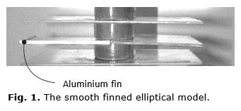
The figure 2, is showing a half fin substituted by an aluminum fin (labeled) having the same dimension than the others. This special fin has its surface cover with naphthalene because previously it was used like a mold to receive melted naphthalene. The surface ofnaphthalene emulated the isothermal boundary condition for the fin during a mass transfer experiment. The surface of naphthalene that is going to simulate the fin surface is obtained by casting using a clean glass plate as a cover to produce a perfect smooth surface. Symmetric flow and heat transfer conditions were considered and only a half fin needs to be substituted. Additional details for the experiment technique could be found in the reference Pérez et al. [4].
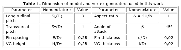
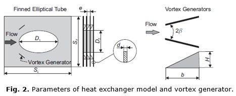
The dimensions of model, took from real heat exchangers, used in air conditioning equipmentand scaling (1:10) to adequate dimensions for collocation of vortex generators arereflected in dimensionless form in the table 1, with reference to the figure 2. SL and ST are the transversal and longitudinal pitches respectively. l is the vortex generator thickness.
In the figure 2, β is the angle of attack, H and b are the height and the base length of vortex generator respectively. Delta shape winglets vortex generators are always used in this work. All dimensionless parameters were obtained with reference to the minor diameter of the ellipse (D2= 6,35 mm). The eccentricity (D2/D1) used was 0,5 because it was found to be the most efficient by Rocha et al. [6].
The experimental procedure consisted in assembling the model with the fin covered by naphthalene, previously, the fin have been weighted. The model was carried to the tunnel and placed into the test section. Immediately, the model was removed and the fin was weighted again. This procedure enabled the measurement of the mass of naphthalene lost by natural sublimation (Δmns) during the manipulation of the model. This value was used later for mass correction because only the mass transferred by forced convection during the test inside the tunnel is relevant. The time wasted in the process of place and remove the model from the wind tunnel was assumed constant for every test. Finally, the fan was turn on and a short warm-up period began. This warm-up is necessary to get a stabilization of the temperature in the test room. After the tunnel warm-up, the fin was weighted before to beplaced with the model into the test section. The chronometer was immediately started. The air temperature was taken every two minutes and the room conditions were also monitored. After 35 or 40 minutes (Δt) the fan and the chronometer were turned off and the model was removed. The special fin was dismounted and weighted again. As result, an initial and a final weight were available. Additionally the time elapsed and the air temperature are available too. If the room temperature changed more than 0.7oC during the test run, thetest was interrupted and the result were not considered. In this work was used a pair of vortex generators having an aspect ratio of equal toone and symmetrically placed in both sides of the tube. A delta winglet vortex generator was chosen and an angle of attack of 45° was initially used. The vortex generators were always placed in common flow down disposition. The experimental procedure is developed for smooth condition (without vortex generators) and using vortex generators.
Data Reduction Procedure
The average Nusselt number was determined as follows. Each set of measurements was processed beginning with the calculation of the mass transferred by forced convection duringthe test (Δm), obtained by the difference between the initial and the final weight of the fin (mi and mf) and considering also the mass lost by natural sublimation Δmns referred earlier. The mass lost by natural sublimation occurs during transportation of the model from the wind tunnel to the scale and vice versa. The mass transferred by forced convection can be calculated using equation (1)
The averaged mass transfer coefficient hm was determined by means of equation (2) considering the time elapsed (Δt) during the test:
]]>
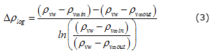
where Af is the fin area covered with naphthalene. The mean logarithmic vapor density was calculated by the following equation (3):
Where the density of vapor at the fin surface level (Ρvw) is calculated using the ideal gaslaw at the surface temperature. The vapor pressure of naphthalene is obtained by means of Ambrose’s correlation. The vapor density of the mainstream at the entrance (ρv∞in ) is considered null because the wind tunnel is open circuit. The vapor density of the main stream (ρv∞aout) at the exit of the channel was calculated using the equation (4).
The denominator of equation (4), (Q) is the volumetric air flow rate in the channel, between two consecutive fins. Therefore, the mass transfer Stanton number could be determined bythe following equation (5):
where u is the average velocity in the minimum free flow area of the channel, function of the flow rate through the tunnel. If the following assumptions are considered: there is not chemical reaction, there is a low rate of mass transfer, the fluid has constant properties and radiation heat transfer is neglected.
Then, from the analogy between the heat and mass transfer we could write as observed in the equation (6) that:
]]> where Sth is the heat transfer Stanton number and the Schmidt number, obtained from Cho’s correlation as function of the surface temperature Tw. The Schmidt number is obtained from equation (7)The Nusselt number was obtained by the equation (8), where the Reynolds number was calculated using the definition of hydraulic diameter of thechannel.
Finally the heat transfer enhancement E was evaluated using an enhancement ratio between the averaged Nusselt number for the augmented (Nu) surface and the smooth(Nu0) surface as indicated by equation (9).
RESULTS AND DISCUSSION
The experimental technique and the procedure used in this work were certified by comparison with experimental results available in the literature. Figure 3 presents the experimentalresults by Ximenesapud Pérez et al. [4], and those obtained in the present work for the same transversal pitch. The values were plotted using the Sherwood number (Sh) to avoid thepossible divergence introduced by the exponent of the heat and mass transfer analogy andthe Schmidt number. It can be said that the present results are in good similar to previousexperiments. Both numbers are based in the hydraulic diameter.
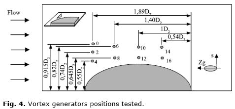
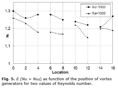
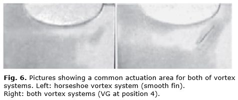
]]> The generators position was varied to sweep the fin surface around the tube. In the abscissas axis, they are plotted numbers from 0 to 16, each one corresponding to a differentvortex generators position identified with the same number at figure 4.Figure 5, presents the heat transfer enhancement results for the finned elliptical tube obtained using vortex generators. The initial results plotted in figure 5, show approximately the same behavior for the two Reynolds numbers tested in this work. Generally speaking, the heat transfer enhancement diminishes when the vortex generators is placed farther from thefin leading edge. The region of vortex actuation is increased gradually when the position is dislocated toward the leading edge of the fin. Therefore, the area with a higher local velocity is larger when compared to the undisturbed region. Additionally, another interesting behavior can be noted in the same graphic, which is the increasing of heat transfer when the location is far from the tube surface. The interaction between the vortex generated by delta winglets and the horseshoe vortex generated in front of the tube should be the reason for this fact. In this situation both vortex systems act in the same region (clearer areas in figure 6, obtained using a visualization process, are indicative of higher mass transfer coefficient). When the vortex generators are placed farther fromthe tube surface, their influence is exerted over a surface area where, in smooth condition,the heat transfer coefficient is lower. In other words, the potential for the heat transfer enhancement is lower when the vortex generator position is closer to the tube surface. The visualization technique used in this work was implemented spreading wetted chalk on a fin surface. The surface with the wetted chalk was exposed to the air flow condition inside the tunnel and the water began to be removed from the chalk. Using a dark background on the fin can be noted clearer areas where the dry process is more intense.
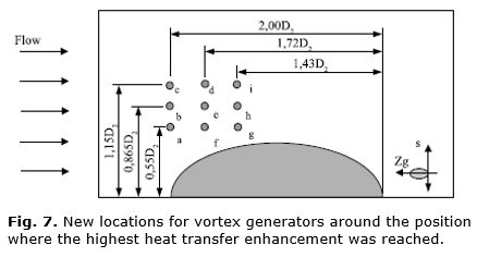
An explanation is necessary for the last positions (14 and 16), because their location isnear the wake region, where there is no influence of the horseshoe vortices and the heat transfer coefficient is low. The vortex generators in this region deviate the flow to the wake region, producing an increment of the heat transfer in this area. Pesteiet al. (2005) reported that placing the vortex generators close to the wake region of a round tube improvesthe thermal performance [16]. Finned elliptical tube with eccentricity of 0,5 presents also are circulation region behind the tube, explaining the results mentioned above. Considering these previous results, another group of experiments were conducted. The area of study wasredefined and the vortex generators were placed only around the position where the highesthe at transfer enhancement was reached in the preliminary experiments. The new locations in tent to redefine the study and they are defined in the figure 7.
In the figure 8, the tests for Reynolds numbers 1600 are presented. In this figure, it can be observed the same tendencies already noted in the analysis of the figure 5: the intensification is increased when the VG location is farther from the tube surface and whenit is dislocated toward the leading edge of the fin.
The points located at larger distances from the leading edge present the lower values for heat transfer enhancement. However, these values are higher than those for points located at the end of the fin in the preliminary experiments (figure 4 and 5). The authors did not seek the locations for the maximum heat transfer enhancement farther from the tubes because it has not practical importance in compact heat exchangers as the vortex generator need tobe placed between tubes.
]]> The influence of the Reynolds number was analyzed for the point where a highest heat transfer enhancement was found. This plot is shown in the figure 9 where the heat transfer enhancement is increased when the Reynolds number is augmented. The ratio Nu/Nu0 did not vary linearly with the Reynolds number, probably because of the short length of the model and the increasing relative importance of the horseshoe vortices system, for higher velocities. The angle of attack of the vortex generator, referred to the main direction of the flow, was varied and five different values were tested for the position "c". The results in figure 10 show coincidence with results of Bayón and Yanagihara [1998] obtained for finned circular tubes. For higher angles of attack the heat transfer increases, reaching a maximum near 55°. When the angle of attack is further increased, a flow deviation occurs instead of a stronger vortex formation.Every configuration of vortex generators tested in this work has associated a pressure drop. Almost in every case the pressure drop will be higher when compared to smooth surface because of a higher frontal projected area. An incremental in drag must be expectedand a combined analysis of pressure drop and heat transfer is necessary to have the whole picture of the problem. In this work it was not studied because the objective was to know the best location considering only the heat transfer. The next step will be to analyze the thermo-hydraulic behavior of more complex geometries having one and two rows of finand elliptical tube.
CONCLUSIONS
Vortex generators enhance the heat transfer when applied to a model of a finned elliptical tube. In the plate-finned elliptical tube, the average mass transfer coefficient was found tobe higher when the location of the vortex generator was closer to the leading edge of the finand farther from the tube surface. The influence on heat transfer of the position of vortexgenerators on the fin surface was investigated and the best result was obtained for the point "c", located at s/D2 = 2,30 and Zg/D2 = 2, referred to the tube (figure 7). The heat transfer enhancement rate obtained at this location should not be considered a maximumbecause it was not detected a diminution beyond it. However, amplification of the rangeof the study has no practical significance because of tube arrangement constraints. The increasing of the Reynolds number always produced higher heat transfer enhancement for the range of Reynolds number tested. Increasing the angle of attack improved the heat transfer behavior but there is a maximum value for this parameter. In summary, it is possible to improve the thermal performance of a plate-finned elliptical tube by the adequate use of vortex generators. The next step includes studies about the influence of built-in vortex generators on the heat transfer and pressure loss of rows of finned elliptical tubes.
REFERENCIAS
1. CHOMPOOKHAM T, et al. Heat Transfer Augmentation in a Wedge ribbed Channel using Winglet Vortex Generators. International Communications in Heat and Mass Transfer. 2010;2(37):163-169. ISSN 0735-1933. DOI 10.1016/j.icheatmasstransfer.2009.09.012.
2. AKCAYOGLU A. Flow Past Confined Delta Wing Type Vortex Generators. Experimental Thermal and Fluid Science. 2011;(35):112-120. ISSN 0894-1777.
3. AIDER J, et al. Drag and Lift Reduction of a 3D Bluff-body Using Active Vortex Generators. Experiments in Fluids. 2010;(48):771-789. ISSN 0723-4864. DOI 10.1007/s00348-009-0770-y.
4. PEREZ R, et al. Thermal and Friction Drop Characteristic of Heat Exchangers with Elliptical Tubes and Smooth Fins. Ingeniería Mecánica. 2012;3(15):243-253. ISSN 1815-5944. Disponible en: http://www.ingenieriamecanica.cujae.edu.cu/index.php/revistaim/article/view/434.
5. FIEBIG M, et al. Local Heat Transfer and Flow Losses in Fin-and-tube Heat Exchangers with Vortex Generators: a Comparison of Round and Flat Tubes. Experimental Thermal and Fluid Science. 1994;(8):35-45. ISSN 0894-1777.
6. ROCHA L, et al. A Comparative Study of Elliptical and Circular Section in One and Two Rows and Plate Fin Heat Exchangers. International Journal of Heat and Fluid Flow. 1997;(18):247-252. ISSN 0142-727X.
7. BORDALO S, SABOYA F. Pressure Drop Coefficient for Elliptical and Circular Sections in one, two and three-row Arrangements of Plate Fin and Tube Heat Exchangers. Journal of the Brazilian Society of Mechanical Science. 1999;4(21):600-610. ISSN 1678-5878.
8. TIWARI S, et al. Heat Transfer Enhancement in Cross-flow Heat Exchangers using Oval Tubes and Multiple Delta Winglets. International Journal of Heat and Mass Transfer. 2003;(46):2841-2856. ISSN 0017-9310.
9. HENZE M, et al. Flow and Heat Transfer Characteristics behind Vortex Generators. A Benchmark Dataset. International Journal of Heat and Fluid Flow Pergamon Press. 2011;1(32):318-328. ISSN 0142-727X. DOI 10.1016/j.ijheatfluidflow.2010.07.005.
10. BISWAS G, et al. Augmentation of Heat Transfer by Creation of Streamwise Longitudinal Vortices Using Vortex Generators. Heat Transfer Engineering. 2012;4(33):406-424. ISSN 0145-7632. DOI 10.1080/01457632.2012.614150.
11. KATTEA WA. An Experimental Study on the Effect of Shape and Location of Vortex Generators Ahead of a Heat Exchanger. Al-Khwarizmi Engineering Journal. 2012;2(8):12-29. ISSN 1818-1171.
12. HE Y, et al. Numerical Study of Heat-Transfer Enhancement by Punched Winglet-Type Vortex Generator Arrays in fin-and-tube Heat Exchangers. International Journal of Heat and Mass Transfer. 2012;(55):5449-5458. ISSN 0017-9310 DOI 10.1016/j.ijheatmasstransfer.2012.04.059.
13. BEKELE A, et al. Heat Transfer Augmentation in Solar Air Heater Using Delta-shaped Obstacles Mounted on the Absorber Plate. International Journal of Sustainable Energy. 2013;1(32):53-69. ISSN 1478-6451.
14. ZHANG L, et al. Compound Heat Transfer Enhancementfor Shell Side of Double-Pipe Heat Exchanger by Helical Fins and Vortex Generators. Heat and Mass Transfer. 2012 (48):1113-1124. ISSN 0947-7411. DOI 10.1007/s00231-011-0959-5.
15. HUISSEUNE H, et al. Performance Enhancement of a Louvered Fin Heat Exchanger by Using Delta Winglet Vortex Generators. International Journal of Heat and Mass Transfer. 2013;(56):457-487. ISSN 0017-9310.
16. PESTEEI S, et al. Experimental Study of the Effect of Winglet Location on Heat Transfer Enhancement and Pressure Drop in Fin-Tube Heat Exchangers. Applied Thermal Engineering. 2005;(25):1684-1696. ISSN 1359-4311. DOI 10.1016/j.applthermaleng.2004.10.013.
Recibido: diciembre de 2015
Aprobado: marzo de 2016
AUTOR
Rubén Borrajo Pérez. Ingeniero Mecánico. Master en ciencia por el ISPJAE. Doctor en ciencias térmicas por la Universidad de Sao Paulo (USP), Brasil. Profesor Titular del centro de estudios de tecnologías energéticas (CETER). Instituto Superior Politécnico José Antonio Echevarría (ISPJAE). Cuba. Email: rborrajo@ceter.cujae.edu.cu.
]]>