Design and Implementation of an Attitude and Heading Reference System (AHRS) using Direction Cosine Matrix
Diseño e Implementación de un Sistema de Referencia de Orientación y Rumbo usando Matrices de Cosenos Dirigidos
Antonio Hechevarría Junco1, José Raúl Machado Fernández2*
1 Especialista en Telecomunicaciones, Departamento de Telecomunicaciones (DTEL), Dirección de Tecnología y Sistemas (DTS), Ministerio del Interior (MININT), La Habana, Cuba.
2 Profesor e Investigador, Departamento de Telecomunicaciones y Telemática, Facultad de Eléctrica, Universidad Tecnológica de la Habana José Antonio Echeverría (CUJAE), La Habana, Cuba. ]]>
*Autor para la correspondencia: m4ch4do@hispavista.com
ABSTRACT
Attitude and Heading Reference Systems (AHRS) are based on fusion algorithms for Micro-Electro-Mechanical (MEMS) sensors Systems in order to obtain the position and orientation of a given entity. These systems are applied mainly in air navigation services, space exploration and creating interactive software for mobile phones. In an effort for avoiding the high prices of AHRS solutions in the international market, the authors construct a device with individual components using the Direction Cosine Matrix (DCM) alternative as fusion algorithm. As a result, the implementation of a functional architecture is achieved at a reduced cost. Validation’s tests were executed observing the effective detection of the Pitch and Roll angles after rotating a surface where the device was situated.
Key words: Attitude and Heading Reference Systems (AHRS), Micro-Electro-Mechanical Systems (MEMS), Algorithms for Sensors Fusion, Direction Cosine Matrix (DCM).
RESUMEN
Los Sistemas de Referencia de Orientación y Rumbo (AHRS, Attitude and Heading Reference System) se basan en el uso de algoritmos de fusión de Sistemas de Sensores Micro-Electro-Mecánicos (MEMS, MicroElectroMechanical Systems) para conocer la posición y orientación de un cuerpo. Encuentran su aplicación fundamentalmente en la navegación aérea, la exploración espacial y la creación de programas informáticos interactivos para teléfonos celulares. Ante los elevados precios de las soluciones AHRS en el mercado internacional, los autores construyen un dispositivo a partir de componentes individuales utilizando algoritmos de Matrices de Cosenos Dirigidos (DCM, Direction Cosine Matrix) en el rol de mecanismo de fusión. Como resultado, se logra implementar una arquitectura funcional a un costo reducido, validada con pruebas donde se midió la detección efectiva de los ángulos de Cabeceo (Pitch) y Alabeo (Roll) colocando la solución sobre una superficie sometida a rotaciones.
Palabras clave: Sistema de Referencia de Orientación y Rumbo, Sensores Micro-Mecánicos, Algoritmos de Fusión de Sensores, Matrices de Cosenos Dirigidos.
INTRODUCCIÓN
ARHS systems provide information about the orientation, the heading and the position of a given body in space (Teixeira Rita 2009). The orientation is specified by the prediction of the Roll, Pitch and Yaw angles, known as Euler angles. Applications of attitude and heading reference systemsare found in the aviation industry for aerial control and navigation (Nerholm 2011; Sevilla Fernández 2014), in the aerospace industry to develop unmanned robots, in the movies for performing three-dimensional planes, in the medicine for patient rehabilitation and body biomechanics researches (Dehzangi et al. 2013; Frisoli et al. 2011), and in video games and cell phones in the form of interactive applications (Castro Pescador 2013).
The classic form of implementing an ARHS consist on placing multiple sensors in order to obtain supplementary information sources that will be integrated using a fusion algorithm (Almeida Cypriano 2014). The most popular sensors are known as MEMS, and are classified as accelerometers, gyroscopes and magnetometers.
An accelerometer is designed to measure acceleration along a predefined axis (Andrejasic 2005). Taking into account the constant contribution of gravity’s acceleration, it can be understood that the sensor provides a mixture of the acceleration experienced by the body during a rotation and the gravitational contribution.
Furthermore, a gyroscope is a device that measures the angular rate experienced by a body along one of the axes of the coordinate system (Piechocki 2012). Gyroscopes are sometimes used to correct measurements made by the accelerometers, or vice versa; both systems are often regarded as complementary.
Accelerometers are sensitive to vibrations experienced by the body on which they rest and consequently introduce an error in measurement caused by the small accelerations that appear in several axes. Therefore, its operation only makes sense in static conditions.
Gyroscopes, on the other hand, provide an effective response in dynamic conditions. If the body is in static conditions, the output signal of the sensor suffers a shift which accumulates as time passes creating errors in the measurements. The shift is a product of the noise that appears in this type of sensor.
The third type of MEMS, the magnetometer, is a device that measures the strength and the direction of the magnetic field, either the Earth magnetic field or one artificially created (Almeida Cypriano 2014). Magnetometers may be scalar or vectorial; the last one allows measuring the field’s direction.
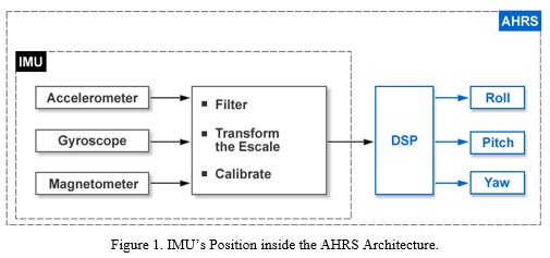
]]> The above described sensors are used within an Inertial Measurement Unit (IMU). An IMU takes the raw values of the sensors and filters the information, transforming it later into units from different physical parameters. Finally, the data is calibrated with temperature because measurements are sensitive to it (Leyton 2009).As it’s shown in Figure 1, an IMU is an important component within an AHRS and the signal obtained at its output is passed through a Digital signal Processing (DSP) block to obtain the roll, pitch and yaw values. Inside the DSP block, estimation and fusion mechanisms are executed in order to fusion the sensors’ contribution. Note that an AHRS solution differs from a traditional Inertial Navigation System (INS) which provides additional information about the speed, in addition to the estimation of the orientation and position (Leyton 2009).
AHRS systems are typically integrated together with electronic flight information systems to build an aircraft’s main flight monitor. In addition, they can be combined with flight data computers in order to materialize what is known as an Air Data, Attitude and Heading Reference System (ADAHRS), which provides extra information like wind speed, altitude and air temperature (Leyton 2009).
Motivation and Objectives
The cost of an AHRS certified by the FAA (Federal Aviation Administration) is quite high, which, together with the American embargo restrictions, make really hard to buy a device for Cuban enterprises. Two of the popular choices in the international market are:
MTI device, Xsens manufacturer, 3 000 EUR (March 2013g).
3DM-GX device, Micro Strain manufacturer, 3500 USD (March 2013f).
In order to facilitate the equipment’s acquisition, the authors set as the goal of the current investigation the building of a device from sensors and other integrated circuits. In addition to the construction, it is also an objective to keep expenses as low as possible, so the alternative will be advantageous when compared to the purchase of commercial equipment. Besides using several individual components, the authors must program a sensors fusion algorithm into a microcontroller, which constitutes the hardest task of the schedule. For achieving this, the most important choices are: Kalman filters and DCM.
Kalman filters have many applications in different estimation problems and are very popular (Castañeda Cárdenas et al. 2013; Cucu 2012; Melero Cazorla 2012; Rodríguez Muñoz 2003), although its implementation is often intricate. Documentation dedicated to them is available in multiple publications (Brookner 1998; Grewal and Andrews 2001).
The DCM method, presented in (Premerlani and Bizard 2009), is based on an IMU to develop applications for airplanes and helicopters. The theory is supported on the necessity of a method that respects the nonlinearity of the rotation group (group of all possible rotations). Similarly, multiple investigations can be found based on this approximation (Piechocki 2012; Sevilla Fernández 2014; Teixeira Rita 2009).
Contributions
Authors choose the DCM method because they believe it is the easiest to implement and fits correctly with the problem at hand. Using this technique, they develop an AHRS device with reduced money expenses, validating its correct performance by checking the effective detection of the Pitch and Roll angles after placing the solution on a surface submitted to rotations.
MATERIALS and METHODS
In this section, the Direction Cosine Matrix method, used in the project as fusion algorithm for the outputs from accelerometers and gyroscopes, is briefly described. Likewise, integrated circuits included in the implementation are presented, facilitating thereby the reproduction of the design.
DCM Algorithm
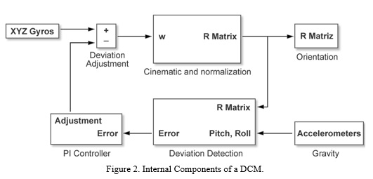
]]> In the current project, a Direct Cosine Matrix algorithm is utilized for the fusion of the contributions from different sensors. Its operation principles are described below.The gyroscopes stand out as the main source of orientation information. By handling their contribution, the authors proceed to integrate the nonlinear differential equation that describes the rotation dynamics, in a process that must be performed at a high speed (Blanc 2013). Numerical integration errors gradually violate the orthogonally restrictions that the DCM must meet; introducing thus some deviations (Macias et al. 2012). Deviations are then mixed with the mistakes corresponding to the shift in the gyroscopes as the error’s magnitude gradually increases.
In order to correct the mistakes, reference vectors and a negative feedback PI (Proportional Integral) controller are employed. Therefore, imperfections are corrected by a faster mechanism that the one that generates them, avoiding the accumulation (Blanc 2013).
Figure 2 shows how a feedback connection is maintained in order to correct the values obtained from the gyroscopes. The feedback information is used by the direction cosine matrix to put together the orientation matrix, which corrects the deviation of the gyroscopes also by employing the contribution taken from the accelerometers. Afterwards, the PI controller performs the adjustment.
Used Components
To complete the device’s design, besides several distributed components, four integrated circuits corresponding to one accelerometer, two gyroscopes and one microcontroller were employed. This section briefly describes them.
ADXL335 Accelerometer
The ADXL335 integrated circuit is a small accelerometer that measures acceleration in the three axes with a minimum full-scale range of ± 3 g (1g = 9.8m/s2). Its output signals are analog voltages proportional to the acceleration measured in each axis (March 2013a).
The signal’s bandwidth is controllable by the user if a capacitor is added. The corresponding filtration produces improvements in the measurements’ resolution and prevents aliasing. The bandwidth may be selected for the X and Y axes from 0.5 Hz to 1600 Hz and for the Z axis from 0.5 Hz to 550 Hz. In the developed design, authors used 0.1μF capacitors establishing a bandwidth of 50 Hz.
]]> LPR530AL and LY530ALH GyroscopesThe LPR530AL integrated circuit is an analog gyroscope capable of measuring angular rate along two axes (allowing to find the Pitch and Roll angles). It has a scale of 300 °/s and is qualified for measuring, with -3 dB of the nominal bandwidth, up to 140 Hz (March 2013b).
The gyroscope is the combination of an actuator and an integrated accelerometer in one micromechanical structure. This structure includes a sensor element composed by a single transmission mass which, maintained in constant oscillatory motion, it is capable of reacting when an angular rate is applied. Finally, a CMOS integrated circuit provides the measured angular rate through an analog voltage output (March 2013b).
The previously described integrated circuit is utilized together with the LY530ALH model, which has a single output, to produce a three-axis gyroscope. The characteristics of both devices are very similar, making them easier to attach.
PIC 18F2525 Microcontroller
Dotted of a high computational development, the 18F2525 PIC microcontroller includes various peripherals such as counters, a serial port and an Analog-to-Digital Converter (ADC) (March 2013c). Thanks to the wide range of options offered, among which it worth highlighting the alternatives for selecting the oscillator, the authors choose the model as the responsible of performing the calculations for estimating the Pitch and Roll angles, besides making effective the correction of the values obtained by the gyroscopes.
For the design of the AHRS device, an external oscillator was used with an output of 16 MHz. The internal elements employed for programming the fusion algorithm were the Timer0, the ADC module, and the EUSART (Enhanced Universal Synchronous Asynchronous Receiver Transmitter)
RESULTS
The current Section shows the final AHRS hardware solution that resulted from a simulation optimized in the PROTEL (PRocedure Oriented Type Enforcing Language) software (March 2013e). Similarly, the sequence of programming steps meant to be executed by the microcontroller, which was developed using CCS C Compiler for PIC18 family through the MPLAB IDE v8.43 software application (March 2013d), is presented.
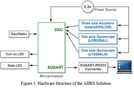
]]> Hardware SolutionFigure 3 shows the hardware structure of the final AHRS solution. It can be observed that the sensors are connected to different channels of the multiplexer of the microcontroller’s DAC. Channels zero and one are occupied by the amplified outputs of the LY530ALH and LPR530AL integrated circuits. The rest of the outputs, which are not amplified, are passed through a high-pass filter consisting of a 4.7 uF capacitor and a 1 M![]() resistor connected to ground, followed by a low-pass filter including a 33 K
resistor connected to ground, followed by a low-pass filter including a 33 K![]() resistor and a 1 uF capacitor. This is done by following the sensors’ manufacturer recommendations.
resistor and a 1 uF capacitor. This is done by following the sensors’ manufacturer recommendations.
In the case of the ADXL335 integrated circuit, 0.1 uF capacitors are attached to its outputs in order to limit the signals’ bandwidth to 50 Hz. The three outputs of this circuit are connected to the channels three, four and eight of the DAC. Channels five, six and seven are only functional in devices having 13 channels in the converter; the ADXL335 has eight channels.
The PIC 18F2525 microcontroller is responsible for processing the data from the sensors and estimating the Pitch and Roll angles, information that will be transmitted via the serial port. The authors connected a personal computer to this port, which allowed to adjust the deviation constants of the PI controller and to observe the behavior of the system after applying different signals.
As it is revealed in Figure 3, two LEDs (Light Emitting Diodes) are incorporated in the schema. One of them turns on when the system is operating and the other one indicates the occurrence of saturation in a gyroscope.
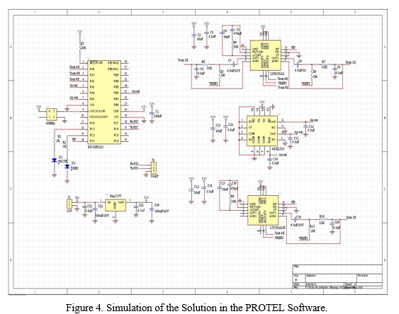
Before implementing the solution, the architecture was tested in PROTEL software (March 2013e)(March 2013e). Figure 4 shows a screenshot of the application where all included elements are displayed.
After simulating the previously described hardware structure and finish testing its correct operation, the authors proceeded to program the microcontroller for performing the sensors fusion by means of the DCM method. The sequence of configuration steps is described below.
]]> Software AlgorithmSoftware development contains everything related to the execution of the functions which together provide the orientation information. The program developed for the PIC 18F2525 microcontroller was achieved in the C programming language, using the CCS C compiler for the PIC18 family, through the MPLAB IDE v8.43 software.
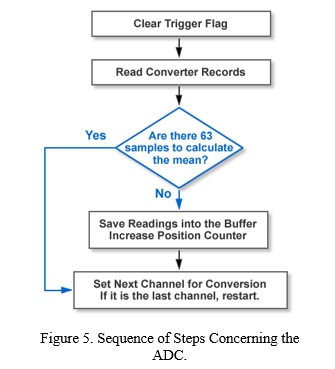
Figure 5 shows the algorithm concerning the ADC. Sensors’ samples are stored in a data buffer for the later averaging of the values. The procedure ensures an increase in the converter’s resolution by performing an oversampling.
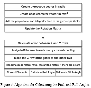
Figure 6 illustrates the algorithm for calculating the Pitch and Roll parameters. The first part of the sequence is intended to update the rotation matrix, being executed for each integration step with the values obtained from the gyroscopes. Renormalization is performed subsequently ensuring that the rows of the matrix are orthogonal between each other and that its length is equal to one. Then the array elements are corrected using the information provided by the accelerometers, and the estimated orientation is finally calculated.
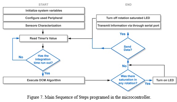
The main execution algorithm is given in Figure 7 where the sequence for de DAC (Figure 5) is incorporated in the step "Read Timer’s value" and the calculation of the Pitch and Roll parameters (Figure 6) appears under the name "Execute DCM Algorithm". This implies that Figure 5, Figure 6 and Figure 7 contain the full sequence programed in the microcontroller.
The hardware scheme and the sequence of programming steps introduced in the microcontroller were described in this section. A more detailed explanation of the methodology followed by the authors can be found in the full-version of the investigation (Hechavarría Junco 2011). The next one makes an evaluation on the effectiveness of the implementation.
DISCUSSION
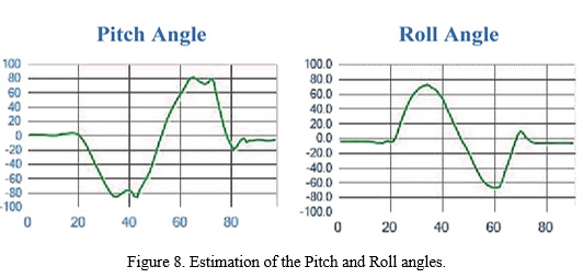
]]> In order to check the correct operation of the built AHRS solution, an application was created in C ++ that reads the PC serial port and plots the Pitch and Roll estimations. Figure 8 displays some resulting draws taken from measurements performed over bodies under rotation. The X axis represents the time in seconds and the Y the rotated angle. Accordingly, the correct estimation of the angles with a resolution of less than one degree is achieved.In addition to the accurately estimation of the Pitch and Roll angles, the constructed device was achieved at a cost 60 times inferior than the commercial alternatives. This justifies the time and efforts invested in the research. Table I splits the price into the cost of each element.
CONCLUSIONS
An AHRS device was created, capable of recognizing the Pitch and Roll angles for a rotating body with very good accuracy. Achieved using a DCM algorithm, the solution was implemented at a cost 60 times inferior than its market price. The main utilized components were the PIC 18F2525 microcontroller, the ADXL335 (Accelerometer) and the LPR530AL (Gyroscope) integrated circuits. The PROTEL software was used for testing before building the device and the sequence of steps programed in the microcontroller was developed in C language with the CCS C compiler through the MPLAB IDE v8.43 software.
RECOMMENDATIONS
The designed system ignores the centripetal acceleration that is originated when describing a circular path. The limitation can be corrected if a GPS (Global Positioning System) receiver is added to the structure. Moreover, the inclusion of a three axis magnetometer for working with the yaw angle would allow providing the magnetic field acting on the body.
The microcontroller used by the authors is not designed to perform calculations with matrices in an efficient manner. Therefore, the use of a model of the PIC 30F family is recommended to facilitate the programming of algorithms in future DCM implementations.
REFERENCIAS BIBLIOGRÁFICAS ]]>
ANALOG DEVICES. ADXL335. [data sheet]. In. http://www.analog.com/static/imported-files/data_sheets/ADXL335.pdf, March 2013a.LPR530AL. MEMS motion sensor [data sheet]. In. https://www.sparkfun.com/datasheets/Sensors/IMU/lpr530al.pdf, March 2013b.
Microchip. PIC 18f2525/2620/4525/4620. [data sheet]. In. http://ww1.microchip.com/downloads/en/DeviceDoc /39626e.pdf, March 2013c.
MPLAB IDE v8.43 In. http://www.microchip.com/forums/m466151.aspx, March 2013d.
Página Oficial de PROTEL. In. http://www.altium.com/, March 2013e.
Precios del dispositivo 3DM-GX, fabricante Micro Strain. In. http://www.microstrain.com/inertial/3dm-gx3-45, March 2013f.
Precios para el dispositivo MTI, fabricante Xsens. In. http://es.farnell.com/Search?storeId=10176&catalogId=15001&langId=-5&st=dev%20kits&sort=P_MAN_BRAND _NAME|1&beginIndex=2, March 2013g.
ANDREJASIC, M. MEMS Accelerometers. 2005.
BLANC, H. Inertial and optical hybrid head tracking for helicopter simulators. 2013.
CUCU, L. Applying Kalman Filtering on a Quadruped Robot. Microengineering, 2012.
NERHOLM, P. A. MEMS Inertial Navigation System. 2011.
PREMERLANI, W. AND P. BIZARD Direction Cosine Matrix IMU: Theory. Edtion ed., 2009.
SEVILLA FERNÁNDEZ, L. Modelado y Control de un Cuadricóptero. Universidad Pontífica Comillas, 2014.
Recibido: 02/11/2015 ]]> Aceptado: 30/05/2016
]]>