


 Custom services
 Spanish (pdf)
 Article in xml format
 Article references
 Send this article by e-mail
 Cited by SciELO
  Similars in
SciELO
Similars in
SciELO 
 Permalink
Introduction
According to what was stated by reference [1],the appearance of electronics revolutionized the concepts related to electricity, since electronic measurement equipment began to reduce the errors associated with these to a minimum fraction compared to electromechanical equipment. Microcomputers began to have faster processing, new interfaces were created, the concept of distance communication became popular; and electronics made it possible to substantially reduce the physical volume of electrical devices, in addition to increasing their efficiency. Currently, technology has been developed on a large scale, so the basis for the use and implementation of new systems is the facilitation of the execution of tasks by man, as well as the possibility of expansion and creation of new markets with the use of machines, automobiles, industries, plants, among others.For its part, in the energy sector, a massive investment in improvements from a technical point of view became necessary, since the population as a whole gained access to more developed household appliances powered by electricity. Therefore, the challenge that electrical power systems have in any country is to maintain reliability, to actively contribute to the sustainability of the energy model and adapt to the changes demanded by users.
In the midst of the growth process of the electrical sector, engineering tries to balance various creative solutions to solve problems keeping in mind the economic factor, since the projects financed by the private sector always aim for the highest possible profit. The increasing use of equipment based on power electronics awakens the importance of the relationship between this area of electrical engineering and the quality of electrical energy. For example, in applications related to direct current (DC) microgrids, the use of DC-DC power converters is generally required. The importance of these electronic devices lies in the need to couple different voltage levels to desired reference values. These DC-DC power converters are widely used in the control of electric motors for cranes, trains, and hoists, as they have high efficiency and fast dynamic response.
On the other hand, motivated by environmental and economic conditions, there is a global trend focused on increasing the use of renewable energy sources. Some of these energy sources are DC, such as photovoltaic systems, in this case, it requires the participation of power electronics in the generation process. This “electronic” generation will progressively reduce the equivalent inertia of electrical systems, favoring a decrease in immediately available stored energy and allowing larger and faster frequency variations to occur in the event of disturbances. To avoid the above, investigations are carried out to obtain the equivalent transient behavior of an equivalent "synchronous generator" through the use of control strategies with the power electronics involved. Which creates a virtual inertia with power converters, to contribute to a more stable electrical power system [2].
This situation, which can present itself as a risk to the electrical system, must also necessarily be connected through power electronics. Through the use of suitable electronic power converters and control systems, it is also possible for renewable generation to assume services normally reserved for traditional generation, such as voltage maintenance, restoration of electrical service after service interruption, etc. In this way, power electronics will help the correct integration of renewable energies, helping to achieve the decarbonization objectives of the sector [3, 4]. In summary, in this new scenario, power electronics becomes an essential actor to achieve the objectives of the energy transition, through the control and transformation of energy, identifying itself as one of the facilitators and key elements for to be able to reach the electrical network of the future. Renewable energy generation systems need power electronics to inject energy into the grid and allow its distribution; In addition, accumulators may be necessary to store the variable production, also connected through this technology. In the transport sector, power converters are also necessary to enable electric traction, since they are an intermediate element that connects the engine with the energy storage equipment in vehicles, playing a fundamental role as a control element of the energy [3, 4, 5, 6].
As stated by the authors of reference [7], one of the objectives of a converter is to obtain a regulated voltage or current starting from an unregulated one. For this, a switch is used that alternates between two sub time intervals that we call on and off at a certain frequency. Counting with a single output and a single input, the interaction between the elements of the converters described here and its modeling is limited to the analysis of what happens in those two-time subintervals that are associated with the operating states of the circuit. It will be working on the continuous conduction mode for the stable state, in which there are two sub-intervals on and off.On the other hand, according to the investigations of reference [8], there are different approaches to model and simulate a DC-DC converter, such as through analytical mathematical expressions, circuits, transfer function and state space. The most common approach is circuit modeling, where the converter circuit topology is drawn directly in the modeling and simulation platform. However, compared to the other methods, there is not much literature on modeling using the state space approach, hence the importance of this research.
Not all modeling methods are suitable for all studies to be carried out. A disadvantage of the models developed with the Laplace transform for transfer functions, is the limits of an input, an output and a linearized model; which does not represent limitation in a representation by means of state space.Based on the above, the general objective of this work is to model using the Scilab software applying the state space method in direct current to direct current converters, as a result the application proposed here for its first version in the which four converter configurations are modeled such as Buck, Boost, Buck-Boost and Cúk topologies.The text was organized in order to initially present in a general way the current situation of the topic addressed, in order to expose the need for the development of computational tools through the use of free software, inserting the reader in the current context, in what refers to the knowledge of modeling from the state space method, taking it to the point of analysis of converters using computer simulation, in order to its practical implementation.
Materials and methods
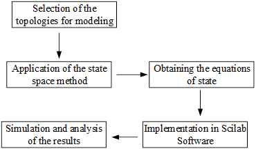
In order to develop the objective of this research, it was necessary to verify the existing theoretical studies and search for scientific knowledge accumulated around the analysis of the models of the most used configurations of direct current to direct current converters for their implementation in the free software Scilab. A total of 15 bibliographic references were consulted, as well as catalogs and technical standards, which allowed the development of the application proposed here using the methodology presented in figure 1.
Discussion and results
According to the investigations of reference [9], it is affirmed that a state space mathematical model is a representation of a phenomenon that is described by means of input, output and state variables, which are related by differential equations in the domain of time. This allows us to form a system of differential equations in the form of a first-order matrix. To be able to determine the behavior of the model before any input stimulus, it is required to know the current state of the system. State variables are all those that contain information on the state of the system one instant before and one after the transient process occurred. Being able to conclude then that: in any physical system, those that allow predicting its future state are called state variables if their values are known at an initial moment, as well as the configuration, parameters and stimuli of said systems.
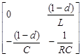
Logically, the state variables have to be continuous, since otherwise, even if their values were known at an instant before the transient process (t0-), their value could not be predicted even at the instant after the transient process (t0+).On the other hand, it is important to point out that in electrical circuits the continuous variables are the currents in the inductors (iL) and the voltages in the capacitors (uC) and therefore these are the state variables in the case of electrical circuits, such as It is shown in the system of equations (1):
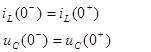 (1)
(1)
In addition, in reference [9], it is stated that the modeling of the state space is fundamentally represented by equations 2 and 3 where: A, B, C, D are the matrices of the system and are formed by constants, in the case of linear circuits, which are the coefficients of the state variables, x: is the state vector and is formed by the “n” state variables that exist in the circuit, x': column matrix that includes the derivatives of all state variables, u: is the input of the system or vector of stimuli that includes all current and/or voltage sources, and y: is the output variable.
 (2)
(2)
 (3)
(3)
State space method applied to converters
In order to explain how the state space method is applied to converters, the Buck converter will be analyzed, with which generality is not lost in the application of the method. A buck converter is a non-isolated step-down DC-DC converter consisting primarily of two energy-storing elements, a controlled switch and an uncontrolled switch, a direct current input source, and the load. The buck converter has two typical regimes in its normal operation: one when the mosfet transistor is in the on state which acts as a closed switch and the other when the mosfet transistor is in the off state which acts as an open switch.
So, when the transistor is in the "on" state the diode does not allow current to flow through it, since it is reverse biased, the source current is the same as the inductor current iL, which is storing energy, like the capacitor C, the equivalent circuit for this state is shown in figure 2 b).Now, when it is in the "off" state, this produces the disconnection of the source u1 from the rest of the circuit, therefore, the source now does not provide current to the circuit. In this configuration, as shown in figure 2 c), the diode is forward biased. If before, the current in the inductor increased, now it decreases. It is important to note that the energy stored in the inductor L and in the capacitor C, is transferred to the load.As already mentioned, the Buck converter topology circuit and its “on” and “off” state equivalent circuits are show in figure 2.

Fig. 2 a) Buck converter topology circuit, b) Equivalent circuit of Buck converter “on” state and c) Equivalent circuit of Buck converter “off” state
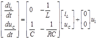
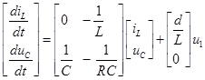
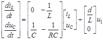
Applying the state space method for each of the Buck converter configurations, finally, the equation in state space when the Buck converter is in the "on" state is as shown in equation (4) and for the “off” state is as shown in equation (5):
 (4)
(4)
 (5)
(5)
In order to obtain the modeling taking into account the commutation duty cycle, that is, "on" and "off" status, it is necessary to find the average matrices A and B, for which the coefficient "d" is introduced, which represents the switching duty cycle. The average matrices A and B are shown, the results are shown in the systems of equations (6) and (7) respectively:
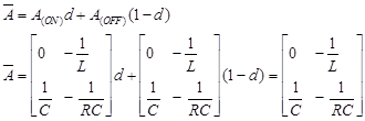 (6)
(6)
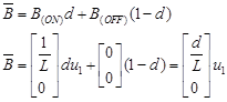 (7)
(7)
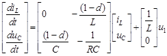
To complete the model of the Buck converter, the average matrix described in equations (6) and (7) are substituted in equation (2), so the state space model of the Buck converter is the one shown in equation (8).
 (8)
(8)
As already mentioned, a similar procedure was applied to the Boost, Buck-Boost and Cúk topologies, the results are summarized in table 1.
Table 1 Results of the application of the state space method in the converters
| Model | Average matrix A | Average matrix B | State equation |
|---|---|---|---|
| Buck |

|

|
|
| Boost |

|

|
|
| Buck-Boost |
|
|

|
| Cúk |

|
|
|
It should be noted that for the development of the models in the state space of each one of the topologies, the investigations of the references were consulted [10, 11, 12].
Implementation in the free software Scilab of the Buck, Boost, Buck-Boost and Cúk converters
Based on the previous analysis and the study of the investigations of the references [13, 14, 15, 16], the application proposed here was developed for its first version implemented in the free software Scilab, which aims to provide a tool, which allows, from simulation, experimentation and demonstration of the functions of CD-CD converters, specifically Buck, Boost, Buck-Boost and Cúk converters, thus contributing to the national development of free computer applications.
In addition, the application is intended to provide a work tool for industrial engineers that allows them to carry out, from modeling, the analysis of the designs of the different applications of the CD-DC converters in order to obtain the best technical variant. and economical for its practical implementation.
Buck converter
Figure 3, shows the graphic interface of a Buck converter, in which the values of resistance, capacitance, inductance and voltage of the source are predefined, in the same way this graphic interface is designed to allow the user to change the data according to their needs. and the result you want to get.
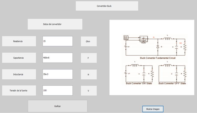
In the lower right part, there is the "Show Image" button which, when pressed, will show the topology of the converter, as well as the equivalent circuits both when it is in on mode and when it is in "off" mode.In the button "Graph" when pressed will show the graphs of the waveforms of the current through the inductor and the voltage through the capacitor. Figures 4 and 5, show the graphs, as examples, of the capacitor voltage waveform against time and the inductor current waveform against time, respectively.


In figure 4, it can be seen how the waveform of the voltage in the capacitor increases until it reaches a maximum voltage peak of 70 V in a time of 0,013 s, then falls until it reaches approximately 42 V in a time of 0,026 s and achieves its stability at 48 V at 0,06 s and thereafter. While in figure 5 it can be seen how the waveform of the current flowing through the inductor with respect to time increases until it reaches a maximum current peak of 6,7 A in a time of 0,008 s, then falls until it reaches approximately the 2 A in a time of 0,02 s and achieves its stability in 3,3 A at 0,076 s and thereafter.
Convertidor Boost
Figure 6, shows the graphical interface of the Boost converter implemented in the free software Scilab, in which the values of resistance, capacitance, inductance and voltage of the source are predefined, this interface is designed so that if the user wishes, he can change the data before mentioned according to your needs and the result want to obtain.
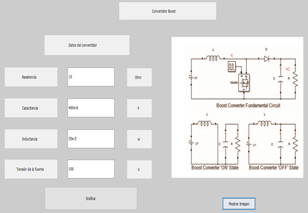
If the "Graph" button is pressed, the graphs of the waveforms of the current through the inductor and the voltage on the capacitor are obtained. Figures 7 and 8, show the waveforms of the capacitor voltage and inductor current against time, respectively.

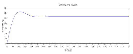
In figure 7, it can be evaluated how the waveform of the voltage in the capacitor with respect to time increases until it reaches a maximum voltage peak of 220 V in a time of 0,027 s, after which it has a voltage drop up to approximately 190 V in a time of 0,06 s and achieves its stability at 197 V at 0,08 s and thereafter.In the Boost converter, the waveform of the current flowing through the inductor with respect to time increases until reaching the maximum current peak of 31 A in a time of 0,02 s, after which it has a slight current drop until approximately 26 A in a time of 0,05 s and achieves its stability at 27 A at 0,07 s thereafter, as shown in figure 8.
Buck Boost Converter
The graphic interface of the Buck-Boost converter implemented in Scilab is shown in figure 9, in which the values of resistance, capacitance, inductance and voltage of the source are predefined, in the same way this interface is designed if the user wishes You can change the data according to your needs and the result you seek to obtain.

By pressing the "Graph" button, the graphs of the waveforms of the state variables of the circuit are obtained, shown in figures 10 and 11, respectively.
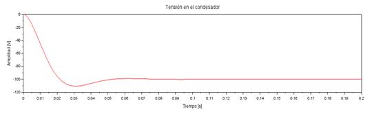
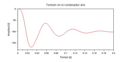
Fig. 10 Waveform of the voltage on the capacitor of the Buck-Boost converter by the state space method
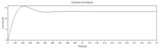
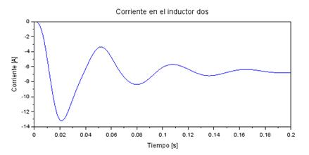
Fig. 11 Waveform of the current in the inductor of the Buck-Boost converter by the state space method
As can be seen, in figure 10, the capacitor voltage waveform with respect to time decreases until it reaches its minimum value at -110 V in a time of 0,03 s, then increases to -100 V in a time of 0,06 s and achieves its stability at -98 V at 0,1 s thereafter.Figure 11, shows the waveform of the current in the inductor, which increases until reaching a maximum current peak of 15,5 A in a time of 0,02 s, then decreases to approximately 13 A in a time of 0,05 s and achieves its stability at 13,5 A at 0,08 s and thereafter.
Convertidor Cúk
Figure 12, shows the graphic interface of the Cúk converter, in which the values of resistance, capacitance one, capacitance two, inductance one, inductance two and source voltage are predefined, in the same way this interface allows the user to change the data according to to your needs and the result you seek to obtain.
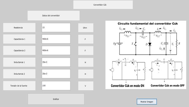
By pressing the "Graph" button, the graphs of the waveforms of the currents through the inductors and the voltages in the capacitors are obtained, shown in figures 13, 14, 15, 16, respectively.
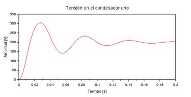

In figure 13, it can be seen how the waveform of the voltage in capacitor one with respect to time increases until reaching a maximum voltage peak of 305 V in a time of 0,028 s, then falls until reaching approximately 140 V in a time of 0,055 s and achieves its stability at 200 V at 0,186 s and thereafter. While in figure 14, it can be seen that the voltage waveform on capacitor two decreases until it reaches its minimum value at -170 V in a time of 0,029 s, then increases to -40 V in a time of 0,05 s and achieves its stability at -100 V at 0,186 s onwards.
On the other hand, the waveform of the current flowing through inductor one shown in figure 15, increases until it reaches a maximum current peak of 24,9 A in a time of 0.015 s, then falls until it reaches approximately -3 A in a time of 0,041 s and achieves its stability at 7 A at 0,189 s and thereafter. In addition, as shown in figure 16, the waveform of the current flowing through inductor two reaches its minimum value at -13 A in a time of 0,02 s, then increases to -3,5 A in a time of 0,051 s and achieves its stability at -7 A at 0,184 s and thereafter.
Conclusions
With the implementation in the free software Scilab of the different topologies that are presented in this work, it was possible to verify that the tools developed in its first version present great practical utility for industrial engineers, since it helps to analyze the design of the parameters to take into account when carrying out its practical implementation. Its potential to model linear systems or not, with several inputs and/or outputs, allows having a general tool to solve electrical circuit problems, which in other cases, require another approach different from the traditional ones. It should be noted that in modern control, the use of state space is becoming more widespread, due to the fact that a greater use of sensors is required in industrial processes.
Applying the state space average model to DC - DC converters facilitates the analysis of the transient process, in addition to the steady state of the converter, but also provides ease of implementation in the free software Scilab.In addition, the software for studies of electrical circuits or mathematical modeling is generally privately licensed, with a high acquisition cost, so its free license equivalents allow a greater reach among students and specialists for purposes.

