


 Custom services
 English (pdf)
 Article in xml format
 Article references
 Send this article by e-mail
 Cited by SciELO
  Similars in
SciELO
Similars in
SciELO 
 Permalink
INTRODUCTION
In the last decade, the wind power integration into power system has increased. This fact is leading to a growing concern about its influence on the operation and stability of a power system [1-2]. Much of these concerns are focused on the impact of wind power integration on voltage [3-4] and frequency stability [5-6], with less attention paid to the small signal stability. The increasing penetration of induction machines as wind generators is bringing concerns on rotor oscillations and stability of induction generators as well as distribution system has been increased.
The influence on the oscillatory frequency and damping ratio depends on the generator model used. In case of squirrel cage induction generator (SCIG), is considered that it has a positive influence on the damping of electromechanical oscillations [7]. However, for doubly fed induction generator (DFIG), applications are not generalized; in some studies the damping is reduced [8] and others report damping increasing [9]. A comparison of both technologies is presented in [10].The results show the best behaviour for DFIG. However, the impact on small signals stability is not only dependent on the wind turbine technology, the system, its configuration, the type of generation and its control system have a strong influence on this, but also on the frequency of oscillation and damping ratio.
Different methods that have been reported for analyzing small signal stability of a power system include probabilistic methods [11], small signals stability region boundary [12], time domain simulations [7], and modal analysis by eigenvalue calculation [8]. The small signal stability analysis with wind power integration has been applied to different power systems. For instance: in IEEE 16 generators 68 buses test system [13], IEEE New England system [14], Uruguayan system [8], and a distribution system interconnected to transmission system [7], are been reported. The scope of this paper is to identify the influence of wind power on the small signal stability of the distribution island system, considering factors such as level of wind power integration, interconnecting point with the electric grid and dispersed wind generation.
MATERIALS AND METHODS
SYSTEM MODELING
In general, elements that should be considered in modeling of a power system for various stability studies are generators, generator controllers, transformers, transmission lines and loads. The modeling approach used in this paper is explained below.
SYNCHRONOUS GENERATOR
In transient stability analysis synchronous generators are represented by sixth order model [15]. Usually synchronous generators are connected to distribution systems as constant active power sources operating at power factor control mode. However, depending upon their capability they may support the voltage by providing the reactive power as well. For voltage control mode reactive power limit has been defined. In the system under study the diesel generators operate as base power providing voltage control.
WIND TURBINE MODEL
Wind power generators available today are classified into the following four main turbine types:
Type A: Fixed speed wind turbine with direct-grid connected induction generator.
Type B: Variable speed wind turbine with variable rotor resistance induction generator directly connected to the grid.
Type C: Variable speed wind turbine with direct-grid connected doubly-fed induction generator and dc/ac rotor converter.
Type D: Variable speed wind turbine with synchronous machine and full scale ac/dc/ac converter.
The selected technology was Type C wind turbine because it is the technology present in the power system under analysis.
Double Feed Induction Generator (DFIG) configuration corresponds to the limited variable speed wind turbine with a wound rotor induction generator and a partial scale frequency converter (rated at approximately 30% of nominal generator power) on the rotor circuit. The partial scale frequency converter performs the reactive power compensation and the smoothest grid connection. The mathematical model can be found in [16].
WIND MODEL
Wind has been modeled as a Weibull distribution, wish is describe as: equation (1).
Where VW is the wind speed, k is shape factor and c is scale factor.
Time variations VW (t) of the wind speed are then obtained by means of a Weibull distribution, as follows: equation (2).
Where
Where V is wind speed on fan hub, Vci is cut-in wind speed, Vco is cut-out wind speed, Vr is rated wind speed and Prd is rated power of wind turbine.
SMALL SIGNAL STABILITY
Small signal stability is the ability of the power system to maintain synchronism when it is exposed to small disturbances [15]. In this context, a disturbance is considered to be small if the equations that describe the resulting response of the system may be linearized. The system used for the small signal stability analysis is a differential algebraic equation set, in the form: equation (4).
Where: equation (5).
Where
The analysis is based on the nonlinear set of system equations, dynamic relations as well as network equations, which are linearized in an operating point to obtain a linear system. Therefore, the nonlinear equations are linearized using Taylor series. The linear result equation is written as (6):
Where A is the system state matrix, B the input matrix, C the output matrix and D the feed forward matrix. Taking the Laplace transformation of equations (6), will result in: equation (7).
The poles of
Equation (8), can be re written as equation (9):
Expansion of the determinant gives the characteristic equation. The n solutions of
The real component of the eigenvalues gives the damping, and the imaginary component gives the frequency of oscillation. Thus, for a complex pair of eigenvalues: equation (10).
Where the frequency of oscillation in Hz, and the damping ratio are given by equation (11) and (12).
Each eigenvalue represents a system mode and the relationship between this mode and the stability is given by Lyapunov [15], where the system is stable when
SYSTEM UNDER STUDY
The system under study is an isolated distribution radial system with a maximum load of 17,7 MW and 6,2Mvar. This load is only supplied by dispersed generation technology. Four 4,5 MVA MAN diesel generators connected at bus 2 and 3, and four 2,36 MVA MTU diesel generators dispersed in the system supply the loads. The main functions of MTU generators are the improvement of quality service and to support the MAN generators at maximum load condition. The distribution system has a voltage level of 34,5 kV and seven distribution substations. System without wind power integration is a base case. In [17], data related with this system is presented. The data related to diesel generators models and the automatic voltage regulator model of MAN technology is according with [17].The base case eigenvalues are computed and 68 eigenvalues with negative real part value are obtained. Some of the most important are shown in figure 1.
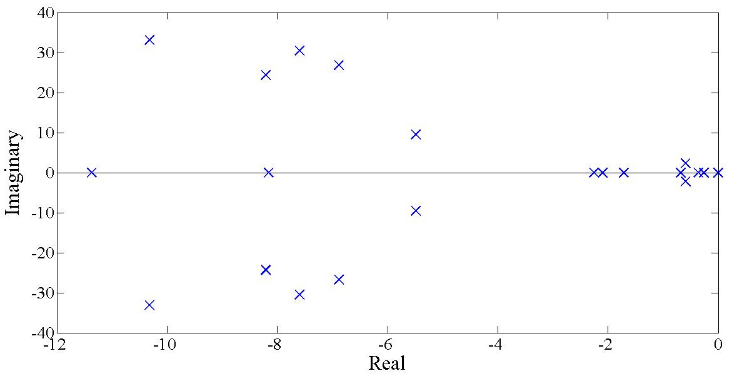
Since all the eigenvalues lie on the left side of the imaginary axis, the system is asymptotically stable. Nine of the eigenvalues are complex, denoting an oscillatory mode. Only the results of the oscillatory mode are shown in table 1. It is interesting to note that the oscillatory frequencies of seven of the nine modes are between 4 and 6 Hz, which is more than the frequency of electromechanical modes of large generators observed in transmission systems, which typical values are between 0,1 and 2 Hz [16].
Some studies in distribution systems also show a frequency of oscillations around 3 Hz [7]. However, these systems are connected to a transmission system through a strong connection link. Other example is the Uruguayan power system [8], with a frequency oscillation of some modes around 3 Hz. Comparing these with the system under study and having into account that the diesel generators are near between them the results of the oscillatory frequencies are logical.
Table 1 Electromechanical mode of the study system
| Modes | σ±jω | Frequency (Hz) | Damping Ratio |
|---|---|---|---|
| Mode 5, 6 | -10,319±33,0976 | 5,518 | 0,298 |
| Mode 7, 8 | -11,8387±34,1594 | 5,754 | 0,327 |
| Mode 9, 10 | -7,5949±30,5123 | 5,004 | 0,242 |
| Mode 11, 12 | -6,8791±26,7876 | 4,402 | 0,249 |
| Mode 14, 15 | -8,2088±24,3146 | 4,084 | 0,320 |
| Mode 16, 17 | -8,2077±24,3217 | 4,086 | 0,320 |
| Mode 19, 20 | -8,2067±24,3288 | 4,086 | 0,320 |
| Mode 25,26 | -5,4895±9,5765 | 1,757 | 0,497 |
| Mode 39,40 | -0,5952±2,2881 | 0,376 | 0,252 |
Source: Authors
The damping ratio is considered poor for values lower than 0,05 according to [8,18]. All damping reflected in Table 1, are above of these values. So, it is possible to say that the distribution system under study has a good damping.
Due to the number of generators and their distribution in the system, it is possible to analyze two local modes and the inter-area mode between area one and area two. A local mode of area one is represented by the MAN generators, according to the participation factors analysis, the major contribution of these generators is in the modes 9 and 10. The area two is represented by MTU generators and the most important mode with less damping ratio is the modes 5 and 6. Finally, the inter-area mode is represented in the modes 14 and 15. The time domain analysis was performed to visualize the rotor oscillations of synchronous generators for base case scenario. For this, a three phase short-circuit fault was applied at bus 8in the second 10 of the simulation and cleared after 70 ms. The rotor speeds of MAN and MTU synchronous generators were observed at figure 2.
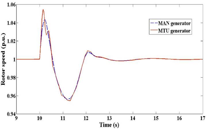
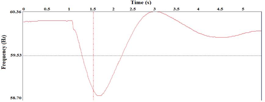
The behaviour for both synchronous generator technologies is very similar. The frequency of oscillation is around 0,35 Hz, corresponding with modes 39 and 40 shown in table 1. In this case, these modes are the dominants and correspond with the excitation system of MAN generators. In order to check this behavior a comparison is make with a real life event occur in the system under study. Figure 3, shows the frequency response of the system against a disturbance. The real frequency of oscillation in the system is around 0,34 Hz, which is also the range shown by eigenvalues analysis. The difference with the simulation is less than a 3%, therefore, the system behaviour and models are validated and the system is ready for the small signals analysis with wind turbines.
SIMULATIONS RESULTS AND DISCUSSION
The worldwide concern on environmental issues and legislative changes is supporting the use of more renewable energy resources which are likely to be integrated to the distribution system in the future. For analyzing the influences of wind farm integration into the system under study, the following topics are analyzed:
Influence of wind power increase on the oscillatory modes without disconnecting diesel generators.
Influence of wind power increase on the oscillatory modes disconnecting diesel generators.
Influence of interconnection point of wind turbines.
Influence of dispersed wind farm on the oscillatory modes.
Time domain simulation.
It is assumed that the wind farm (WF) is connected to the system through a line with a resistance of 0.292 pu and a reactance of 0,267 pu, with the same bases of Appendix A. The wind farm consisting of type DFIG wind turbines with a total capacity of 2 MW is connected to the grid. The power is injected into the grid at unity power factor. This is achieved through the pulse-with modulation frequency converter between the rotor of the generator and the grid. The used model of this technology is presented in [17].
INFLUENCE OF WIND POWER INCREASE ON THE OSCILLATORY MODES WITHOUT DIESEL GENERATORS DISCONNECTED
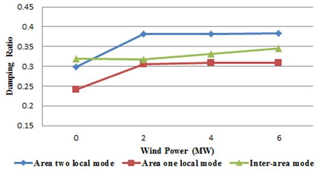
A wind farm made up of DFIG is connected to bus 19. The starting power of wind farms was 2 MW, and the same is increased to 2 MW while the output power of the MTU generators is reduced to its limits, and then was reducing the power output of MAN generators, by the same amount so that the total power remains the same. The damping of oscillatory modes chosen for the study is presented in figure 4, and the oscillatory frequency in table 2. The maximum wind power which was possible to integrate under these conditions was 6 MW.
 Source: Authors.
Fig. 4 Influence of wind power increase using DFIG on the damping of electromechanical mode
Table 2 Oscillatory frequency for increase wind power
| Wind farm | Area One | Area Two | Inter-area |
|---|---|---|---|
| Base Case | 5,004 | 5,518 | 4,084 |
| 2MW | 4,826 | 5,354 | 4,095 |
| 4MW | 4,846 | 5,359 | 4,072 |
| 6MW | 4,853 | 5,356 | 4,062 |
Source: Authors.
The results show that damping of the inter-area frequency mode slightly increases when the wind farm capacity is up to 6 MW while the local modes are positively influenced. The increase of damping ratio of area one was a 29% and for area two was 28%. The oscillatory frequency in area one and two for DFIG wind farm up to 6 MW decreased, while in inter-area mode it slightly decreased.
INFLUENCE OF WIND POWER INCREASE ON THE OSCILLATORY MODES WITH DIESEL GENERATORS DISCONNECTED
Normally, conventional units can be replaced by wind power capacity. In this section an increase of wind power means a shutdown of a diesel generator, starting for MTU technology, except the MTU generator at bus 12, this way keeping the voltage nearby between limits. When three of the four MTU are disconnected and the wind power is continuously increased, it is necessary to disconnect a MAN generator. When DFIG wind turbine is connected the damping ratio of area one local mode is practically constant around 0,25 until a wind farm of 6 MW; for 8 MW the damping ratio rise to 0,34. At this point the system is working with all MAN generators and the MTU generator at bus 12. When the installed capacity of wind farm is up to 10 MW, one MAN generator at bus 3 is disconnected. At this condition, the wind farm substitutes a synchronous machine with excitation system. Therefore, the damping in area one is affected and has a reduction down to 0.3.
The integration of DFIG wind turbine up to 10 MW improves damping ratio and reduces the oscillatory frequency of the system under study. Under this condition, the system is stable for small signal, as is shown in figure 5, with a real negative part for all eigenvalues.

The damping of area two is the same when the wind farm is up to 10 MW, notes that the wind farm is interconnecting to the system in area two; in some way the wind farm integration in this area substitute the damping lose for the disconnection of diesel generators. The inter-area damping is slightly increased up to 0,34.
A decrease in the frequency of the oscillation in area one from 5 to 4,28Hz (15% of reduction) is observed. In area two, the reduction of the oscillatory frequency was 5%, while the inter-area mode frequency is mostly the same for all values of wind farm integration.
INFLUENCE OF THE INTERCONNECTION POINT OF WIND TURBINES
To study the influence of change in wind generator locations on the small signal stability of a power system, the 4 MW wind farm was connected in different buses. In these cases, no diesel generators are disconnected in the power system. The results are presented in table 3.
Table 3 Damping and oscillatory frequency for a 4 MW DFIG wind farm
| Wind farm location | Area One | Area Two | Inter-area | |||
|---|---|---|---|---|---|---|
| Damping | Freq.(Hz) | Damping | Freq.(Hz) | Damping | Freq.(Hz) | |
| Bus 10 | 0,307 | 4,828 | 0,381 | 5,360 | 0,333 | 4,067 |
| Bus 14 | 0,307 | 4,827 | 0,382 | 5,355 | 0,332 | 4,070 |
| Bus 19 | 0,309 | 4,846 | 0,382 | 5,359 | 0,332 | 4,072 |
| Bus 26 | 0,308 | 4,824 | 0,383 | 5,352 | 0,331 | 4,075 |
| Bus 28 | 0,307 | 4,825 | 0,383 | 5,352 | 0,332 | 4,074 |
| Bus 33 | 0,315 | 4,912 | 0,383 | 5,345 | 0,330 | 4,090 |
| Bus 36 | 0,307 | 4,830 | 0,381 | 5,357 | 0,333 | 4,064 |
Source: Authors
For a 4 MW wind farm with DFIG technology the interconnection point does not influence in the damping ratio and the oscillatory frequency. Both parameters are nearly the same for all area modes at any wind location.
INFLUENCE ON THE OSCILLATORY MODES OF DISPERSED WIND FARM
Normally, in distribution system the interconnection of renewable energy resources is dispersed into several points of the grid. The influence of dispersed wind farm in damping ratio and the oscillatory frequency of every mode is analyzed. The comparison was made between a 6MW wind farm concentrated at bus 19 and six wind farms of 1MW at buses 10, 14, 19, 26, 28 and 33.The results are shown in table 4.
Table 4 Frequency and damping ratio for a DFIG wind farm
| Wind farm | Damping ratio | ||
|---|---|---|---|
| Area One | Area Two | Inter-area | |
| Concentrated | 0,309 | 0,383 | 0,346 |
| Dispersed | 0,308 | 0,379 | 0,349 |
| Oscillatory frequency | |||
| Area One | Area Two | Inter-area | |
| Concentrated | 4,853 | 5,356 | 4,062 |
| Dispersed | 4,845 | 5,359 | 4,038 |
Source: Authors
In all cases, damping ratio and the oscillatory frequency are very similar for local and inter-area modes.
TIME DOMAIN SIMULATION
In order to check the behavior of synchronous generators with the integration of wind energy a time domain simulation is carried out. The analysis was making for the most critical condition; correspond with the second scenario, in other words, the scenario when the diesel generators was disconnected in behalf of wind turbine integration. In this case, the wind farm is 10 MW and represents the bigger wind penetration in all studied cases. For the analysis a three phase short-circuit fault was applied at bus 8 and cleared after 70 ms. The rotor speeds of MAN generators were observed at figure 6.

The connection of a 10 MW wind farm improve the MAN generator response, the rotor speed have a better behavior with less peak, less oscillation and better frequency of oscillation.
CONCLUSIONS
The small signal stability of a distribution system with integration of DFIG wind farm was investigated. For base case were observed frequency oscillation modes with roughly 5 Hz. The system has a good damping ratio for both local and inter-area modes and is stable for small signals. The wind farm integration improves the damping ratio and reduces the oscillatory frequency of area one, area two and inter-area mode. A difference is found when diesel generators are disconnected, due to the integration of wind power. For a DFIG wind farm is possible to integrate 10 MW. An improvement in damping ratio and a reduction in oscillatory frequency is observed when is compared to the base case. The interconnection point of wind farm with the system and the dispersed wind farm integration has no significant influence in damping ratio and the oscillatory frequency of local and inter-area modes.

