


 Custom services
 English (pdf)
 Article in xml format
 Article references
 Send this article by e-mail
 Cited by SciELO
  Similars in
SciELO
Similars in
SciELO 
 Permalink
INTRODUCTION
In tropical countries, air-conditioning systems provide comfortable indoor environmental conditions in buildings. These systems typically present a high energy consumption. Air-cooled chillers are largely used in domestic and commercial facilities. In order to reduce their consumption, it is necessary to have efficient systems and operate them properly. Therefore, it is convenient to analyze and simulate a cooling facility in order to improve its energetic performance to understand their energy efficiency [1-4]. In hotels in Cuba, air-cooled chiller systems are preferred and consume about 65% of the total electricity consumption [5-7].
Air-conditioning systems generate a lot of condensation heat (around of 1,25 times the cooling capacity), which may be recovered to provide sanitary hot water [4]. The integrated system thus offers air-conditioning and hot water at the same time, in contrast to conventional systems where space cooling and water heating is achieved independently and hot water is provided by an individual electric or natural gas fueled boiler. Combined cooling, heating, and power systems can achieve highly efficient utilization of energy by using waste heat recovery technology. It has the advantage that the sanitary hot water is produced from the condensation heat of the chiller and heat pump. The combined system improves the overall performance and enhances the technology [8-13].
Waste heat recovery technologies reduce the overall energy consumption. Air-conditioning systems are good for low-temperature waste heat recovery, as they give the capability to upgrade waste heat to a higher temperature and quality. Sanitary hot water can be achieving by recovering about 20% of the total rejected condensation heat, also the COP of the system could be increased [14]. Imbert [15], demonstrated that the COP of an industrial refrigeration installation could be improved, and the costs of water heating reduced by installing a heat recovery system. A thermodynamic simulation for a single stage centrifugal chiller with a heat exchanger between the compressor outlet and the condenser to supply hot water in a hotel in South China, was developed by [16], and showed that the combined system of the chiller unit is very useful in hotel buildings. It is therefore important to discover the maximum amount of recoverable heat for the highest potential of the process and to ensure the achievement of the maximum efficiency from a waste heat recovery system [14].
Sanitary hot water usage (SHW) accounts for a significant share of energy consumption in different types of buildings. The existing guidelines for the water demand of non-residential buildings are outdated and do not include the SHW demand [17,18]. The lack of information also complicates the appropriate design of hot water generation systems and optimal selection of the type and size of the water heating devices [19]. Naldi et al. [20], developed a numerical model for the seasonal performance evaluation of electric heat pumps taking into account the production of sanitary hot water (SHW) warranted using condensation heat. The results show that the primary energy consumption of the system is lower than that of traditional cooling and SHW devices (even more than 30%). Hiller and Johnson [21,22], did some research on the water and energy consumptions in the hotel sector, and found that the SHW system is one of the major end users of the energy and water. Another study on hot water production in hotels in Cyprus was develop by [23]. The results show that the combination of air-source heat pumps with flat plate solar collectors leads to the lowest primary energy consumption compared with the uses of boiler systems that are currently in use in almost all four and five star hotels. The authors highlight the use of solar thermal systems in combination with air-source heat pumps. This paper focuses on energy performance modelling of a combined system that simultaneously provides air conditioning and sanitary hot water in a hotel in Cuba. The utility of this type of systems for hotels is analyzed.
MATERIALS AND METHODS
Heat recovery equipment is commonly used for the production of sanitary hot water (SHW) in hotels, with centralized air-conditioning systems. Heat recovery includes a new element in the refrigeration cycle although the production of chilled water remains the main function. A typical scheme of a refrigeration system with heat recovery is shown in figure 1.
In addition to the basic components of a vapor compression system, a heat recovery is incorporated at the compressor outlet. This element is also known as a desuperheater and is usually a tube and shell or plate heat exchanger. Its function is to transfer the heat of the refrigerant gas that comes from the compressor at high temperature to the water in a closed loop. Subsequently, the refrigerant goes to the condenser at a lower temperature where it finally condenses until it reaches the sub-cooled liquid state and completes its process in the expansion valve to repeat the cycle again. Although promising from a theoretical point of view, heat recovery has disadvantages including the need for additional backup devices because of the limited heat available during partial load performance, the temporal mismatch between cooling load and sanitary hot water load, and the limited functioning during the winter season [24].
Chiller performance
The thermodynamic model is based on an existing plant with an air-cooled chiller with a nominal capacity of 505 kW serving a hotel. A general scheme of the system is shown in figure 2. The chiller has a shell and a tube liquid evaporator designed for a temperature of 3°C. It produces chilled water at a fixed flow rate of 22 kg/s in all operating conditions. The chilled water is supplied at 8,9°C (T10) and returns to 11,5°C (T9) at full load. The heat rejection capacity of the air-cooled condenser controls the condensation temperature at about 47°C with an outdoor temperature of 35°C. In the figure 3, (T13) and (T14) are temperatures at inlet and outlet of the condenser.
The system has two circuits connected by a plate heat exchanger. In the combined system, the chiller is coupled with the primary hot water circuit by the heat recovery, where the superheated refrigerant transfers the heat to the sanitary hot water that is subsequently transferred to the water of the secondary circuit using the plate heat exchanger. In case the temperature of the water at the outlet of the heat recovery is below 60 °C, an auxiliary heater starts operating. Finally, sanitary hot water can be sent directly for consumption, or stored in insulated tanks.
Model
The current study at steady-state conditions is based on the following assumptions:
The pressure drop in the heat exchangers is negligible (evaporator, heat recovery and condenser).
The pressure drop is negligible at the inlet and the outlet of the compressor;
The throttling of refrigerant at the expansion valve was assumed to be isenthalpic (constant enthalpy).
Superheating and subcooling of the refrigerant is assumed to be 8 and 5°C, respectively, for all operating conditions.
There is not heat exchange between the chiller and its surroundings. This means that the heat rejection (Qcond) is the sum of the cooling capacity (Qenf) and the compressor power (Ptot).
Pressure losses in the refrigerant pipelines are negligible.
The model (figure 3), describes the procedure based on the thermodynamic modeling of the elements of the system. The input variables, thermodynamic properties and operating conditions are listed in table 1.
Table 1 Input parameters
| Parameter | Unit | Parameter | Unit |
|---|---|---|---|
| Suction pressure | Ps (bar) | Primary water flow circuit | mprim (kg/s) |
| Discharge pressure | Pd (bar) | Secondary water flow circuit | msec (kg/s) |
| Superheating Temperature | sc (°C) | Hot water return temperature | Tret (°C) |
| Subcooling Temperature | se (°C) | Replacement water temperature | Trep (°C) |
| Total power input | Ptot (kW) | Ambient temperature | Tamb (°C) |
| Enthalpy | h (kJ/kg) | Chilled water temperature | Tch (°C) |
| Entropy | s (kJ/kgK) | Inlet water temperature to heat recovery | T6 (°C) |
The next section details the thermodynamic equations of the model. In the case of heat exchangers, energy balances are defined. Finally, at the end of the model, the thermal potential in the condensation process (Q cond ), the amount of heat recovered (Q rec ); the percentage of heat recovery (n), and the exit temperature of the sanitary hot water (T swh ) are obtained.

Compressor
Knowing the suction and discharge pressures of the system and the temperature of the refrigerant at the inlet, the temperature at the compressor discharge is determined by [25] in equation (1).
Where: p1 and p2 are the suction and discharge pressures respectively, T1 and T2 are the compressor inlet and outlet temperatures respectively in Kelvin, n is the polytropic index. The temperature at the suction of the compressor is given by equation (2).
Where Tev is the evaporation temperature of the refrigerant and Tsc are the superheating degrees refrigerant at the compressor suction.
Heat recovery model
Heat recovery rate and maximum heat transfer is described by equation (3) and (4) respectively:
Where T2 and T6 in (°C) are the refrigerant and water temperatures at the inlet of the heat recovery, respectively; m is mass flow of refrigerant (kg/s); Cp is specific heat of refrigerant (kJ/kgK); ε is thermal effectiveness of heat recovery.
Condenser model
The total heat of the condensation as a process, consists of two parts, the recovery heat (Qrec), and the heat rejected (Qrej). The amount of heat recovered is given by the enthalpy difference of the refrigerant from the compressor outlet (point 2) to the condenser inlet (point 3). According to diagram (T-s) of figure 4. Cycle 1-2-3-5-6-1 shows a refrigeration cycle. Process 1-2 is isentropic compression. Process 5-6 is an isenthalpic expansion and process 6-7 is isobaric cooling. The cycle is working with superheating (form point 7- to point 1) and subcooling regions (process 4-5).
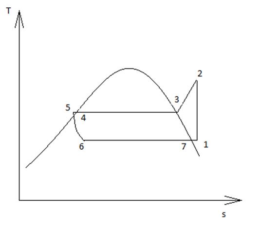
The heat rejected is the enthalpy difference from point 3 to the state of saturated liquid (point 4). The total heat of condensation (Qcond) can be calculated by equation (5):
Model to determine the total heat of the condensation
This section describes a model to determine the heat potencial rejected by chiller. Statgraphic program is used to obtain an empirical model that describes the behavior of the condenser from outer measurable variables such as electrical power (Ptotal), ambient temperature (Tamb) and chilled water temperature (Tch). With the model the calculation is simplified that in traditional way would involve the properties at each point of the cycle.
Based on the data provided by the manufacturer and the data of the actual measurements of operation, it is possible to adjust a surface model to determine the total heat of the condensation as a function of the dependent variable. The modelling for heat rejection is described in equation (6):
Where a, b, c, d, e, f, and g are regression coefficients which can be determined for the chiller by measured or manufacturer data.
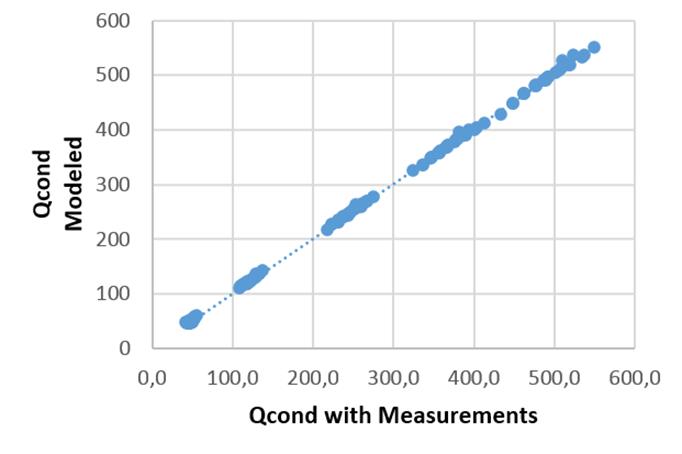
For the validation of the results, the values provided by the manufacturer and those estimated by the model are compared. For the model used in the estimation of the condensation heat it offers a correlation of R2 = 99,9 which indicates a good quality in the prediction of the Qcond variable. (figure 5)
Hot water supply temperature determination.
From the balance equation, the outlet temperature of the hot water to consumption is determined by equation (7).
Where: Qshw, is the sanitary hot water demand, (kW); mshw is the sanitary hot water flow, (kg/s); Cp is specific heat of liquid water, (kJ/kg°C); Tshw is the sanitary hot water supply temperature, (°C); Tmix is mixture temperature of water, (°C).
Determination of the thermal hot water demand
The thermal hot water demand is determined taking into account the flow of hot water that is consumed and the difference between the temperatures of the supply and return flows of hot water to the plate heat exchanger.
The temperature of the mixture (Tmix) is determined as a function of temperature and replacement flow, and temperature and return flow, by energy balance with the equation (8):
Where: Qmix is heat rate of the mixture, (kW); Qrep is heat rate of replacement water, (kW); and Qret is heat rate of return water, (kW).
Mass flows balance is obtained by equations (9) and (10).
Where: mmix, mrep and mret are mass flow rates of mixture, reposition and return water, respectively, in kg/s. Temperature of return water is Tret, and temperature of reposition water is Trep in (°C).
Isolating Tmix from equation (10), as shown in equation (11):
Where: mret is the water return mass flow, (kg/s); mrep is the water replacement mass flow, (kg/s); Tret is water temperature of return, (0C); Trep is water temperature of replacement, (0C), and Tmix: The temperature of the reservoir water mixed with the replacement water.
Coefficient of performance of the system with heat recovery
This system, as it is not a conventional one; its coefficient of performance (COP) is determined as the sum of air conditioning and heat recovery capacities between the chiller total power, see equation (12).
Where (Ptotal) is the total electric power of the chiller in kW, which is the sum of the power of the compressor and the fans of the condenser.
In the model, the thermal exchange between the chiller and the surroundings (environment) is neglected. This means that the total heat transferred to the condenser (Qcond) is the sum of the compressor power (Pcomp) and the cooling capacity (Qevap). The cooling demand can be estimated from equation (13), [25].
Measurements
Operating variables, such as pressures in the suction and discharge line, supply and return chilled water temperature and refrigerant temperature at heat recovery outlet, were monitored by the chiller. PT100 type temperature sensors measured the ambient temperature with a precision of 0,15°C. The flow of sanitary hot water to the system was measured using a magnetic flow meter with an error of 2%. A power analyzer with a precision of 1% of reading was used to determine the chiller power. The measurements were made during one week, during days of low temperature and high occupancy of the hotel (13 to 19 November); in high season of tourism in Cuba.
RESULTS AND DISCUSSION
The SHW profile for typical winter days described in figure 6. The early morning is not considered since there is no consumption; only the recirculation pump operates.
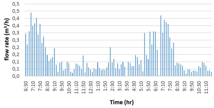
Between 9:00 a.m. and 4:00 p.m., the hot water demand is low, which corresponds with the sanitary hot water profile, however, there is a thermal potential saving from the chillers. During this period, the heat absorbed by the heat recovery behaves unstable, because of repeated starts and stops in the compressors. In the evening, when the room occupancy increases although the cooling demand is much lower due to the low ambient temperature in winter, there is a high peak of hot water use that it is not covered by the heat recovered from the chillers. In these cases, the use of auxiliary heating is needed during this period to raise the water temperature.
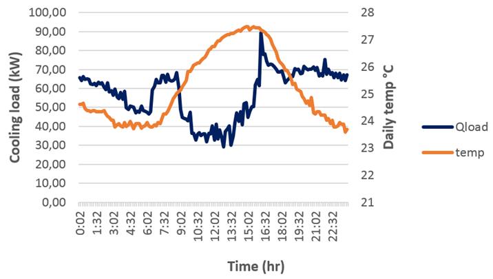
Figure 7, corresponds to the cooling demand of the air conditioning system (obtained from equation 13) and ambient temperature profiles developed from real measurements data. There are two significant peaks of energy (Q load ) in the morning and afternoon hours, coinciding with the arrival of tourists to the hotel.
According to the manufacturer's information for nominal operating conditions of the system working with Tamb = 35 °C, Tch = 7 °C, the nominal capacity of the heat recovery is 23,7% of the total heat of condensation (Qcond) and COP value is 2,78. Under the actual operating conditions for the system, it is possible to estimate the amount of heat recovered in the unit, and to check with the modeled value from the actual operating parameters. (table 2).
Table 2 Operational performance
| Parameter | Operational performance | ||
|---|---|---|---|
| Nominal load | Actual load (Max) | Actual load (Min) | |
| Total Chiller power (kW) | 181 | 90 | 30 |
| Cooling capacity (kW) | 505 | 252 | 50,5 |
| Total Heat rejected (kW) | 668 | 371 | 80,5 |
| PLR | 1 | 0,5 | 0,1 |
| Heat recovery (kW) | 158 | 79,2 | 16,1 |
| Recovery % | 23,6% | 21,3% | 20% |
| COPtotal | 2,78 | 3,68 | 2,22 |
Under actual performance the system operates below its nominal capacity due to the outside temperature and the oversized equipment. The model obtains reliable results according to the operation, recovering around 20% of the total heat rejected for the sanitary hot water production (figure 8), with high efficiency, COPtotal = 3,68. But, as expected, thermal potential available is insufficient in high peaks demand hours due to the lower demand of cooling capacity during all day, so auxiliary heating is needed.

Therefore, it is suitable to evaluate the auxiliary heating devices with an analysis from an economic and environmental point of view for the selection of the most appropriate option. This topic may be the subject of future research studies.
CONCLUSIONS
The total amount of heat rejected by the condenser is estimated from measurable external variables, such as: electrical power, ambient temperature and chilled water temperature, obtaining the total thermal potential available at each moment from existing operation parameters.
The model does not consider properties of the work substance which simplifies calculations, that in traditional way, involve the determination of enthalpies in different points of the refrigeration cycle.
The model predicts the chiller performance for a wide range of operating conditions with good accuracy, and includes an efficiency indicator that consider the combined system of air conditioning and hot water production.

