


Mi SciELO
 Servicios personalizados
Servicios Personalizados
Articulo
 Inglés (pdf)
 Articulo en XML
 Referencias del artículo
 Enviar articulo por email
Indicadores
-
 Citado por SciELO
Links relacionados
-
 Similares en
SciELO
Similares en
SciELO
Compartir

 Permalink
Ingeniería Mecánica
versión On-line ISSN 1815-5944
Ingeniería Mecánica vol.18 no.3 La Habana sep.-dic. 2015
ORIGINAL ARTICLE
The influence of cutting speed and feed rate in surface integrity of aisi 1045
Influencia de la velocidad de corte y la velocidad de avance en la integridad superficial del acero aisi 1045
Mario Jacas-CabreraI, Tania Rodríguez-MolinerI, José Luís Lopes-Da SilveiraII
I Instituto Superior Politécnico José Antonio Echeverría, Facultad de Ingeniería Mecánica. La Habana, Cuba
II Universidade Federal do Rio de Janeiro. Mechanical Engineering Department/COPPE and Poli. Rio de Janeiro, Brasil
ABSTRACT
The aim of this research is to study the influence of cutting speed and feed rate on surface integrity of AISI-1045 subjected to a turning process. The specimens were in annealed condition (81 HRB). A 32 factorial experiment design was employed using low, medium and high levels of the two variables in study, performing 9 experiments with a replica. The surfaces were evaluated through the measurements of surface roughness, surface residual stresses, nano-indentation hardness and analyzing the deformed layer. Results corroborated the great influence of feed rate on surface roughness. The results of the residual stresses have shown the influence of cutting speed as well as feed rate in the behavior of circumferential and axial stress respectively. From the analysis of the microstructure was feasible to observe the tertiary deformation zone due to the machining process. The hardness measured by nano-indentation showed that the thickness of this hardened zone can reach up to 50 µm.
Key words: superficial integrity, surface roughness, nano-indentation, surface deformation.
RESUMEN
El objetivo de esta investigación es el estudio de la influencia de la velocidad de corte y la velocidad de avance en la integridad superficial del acero AISI-1045, sometido a un proceso de torneado. Las probetas se sometieron a un tratamiento térmico de recocidos (81 HRB). En el trabajo se empleó un diseño experimental 32, con dos variables a tres niveles experimentales, para un total de nueve experimentos, los que fueron replicados. La integridad superficial fue evaluada con la medición de la rugosidad superficial, las tensiones residuales superficiales, la medición de dureza por nano–indentación y por el análisis de la de formación terciaria. Los resultados determinaron la gran influencia de la velocidad de avance en la rugosidad superficial. La medición de las tensiones residuales mostró la influencia de las variables de corte. Del análisis microestructural se observó la existencia de dos zonas de deformación determinándose que el espesor de la zona endurecida llegó a 50 µm.
Palabras claves: integridad superficial, rugosidad superficial, nano-indentación, superficie deformada.
INTRODUCCIÓN
Soft machining followed by heat treatment processes have been for many years a conventional method for producing precision parts. Finishing processes with the use of rough and fine grinding is applied most of the times letting the part in a ready to use condition. In order to increase production flexibility, manufacturers have realized the potential of replacing grinding operations with hard turning. This process can be a suitable technology for the production of small lots, Jacobson [1]
The use of hard turning, precise a good knowledge of the integrity of the surface created by the turning process rather it has been hardened or not. Surface integrity has been defined in the past as the relationship between the physical properties and the functional behavior of a surface. Surface integrity is formed by geometric values of the surface like surface roughness, and by physical properties such as residual stresses, hardness and structure of the surface layer.
Several authors have devoted their efforts to study, in different materials, the effects of the cutting regime on the surface integrity. Regarding roughness, there is mostly coincidences in the analysis of the influence of cutting speed and feed rate in this parameter.
Bouacha [2], using bearing steel (AISI 52100), machined at higher cutting speeds, claimed a strong influence of feed rate and cutting speed and a negligible influence of depth of cut. Asilturk [3] and Bordin [4], declared a strong influence of feed rate in surface roughness, based on experiments using AISI 4140 steel and CoCrMo alloy respectively.
In recent studies Aouici [5], using hardened steel AISI H11, concluded that in a machining process the best roughness results were obtained with high cutting speeds and low values of feed rate.
Turning is a complex machining process where plastic deformation with the subsequent material work hardening takes place. Temperature increments constitute together with plastic deformation, sources for residual stresses. These stresses are part of the machined surface integrity.
It is a well known true; that thermal effects tend to generate tensile residual stresses, while mechanical influences contribute to compressive residual stresses Axinte [6]. In the literature analyzed, some controversial behaviors have been reported in relation to the influence of cutting parameters on residual stresses.
Jacobson [1], who studied bainitic steels at a cutting speed of 170 m/minagrees, concluding that an increase of cutting speed, produces a decrease of compressive stresses due to the increased quantity of heat produced at the cutting process, Gunnberg [7], machining 18MnCr5 steel (110-230 m/min), refers that an increase in cutting speed increases tensile stresses in the work piece surfaces, as well as an increase on feed rate generates high compressive residual stresses. Pawade [8], studying the machining of Inconel 718 indicated that with an increase in cutting speed in the 125-300 m/min interval, the residual stresses increased in the direction of traction. However, an increase in the 300 to 400 m/min interval changed the residual stresses direction from tensile to compression.
Regarding feed rate, Pawade, claimed that increases from 0,05 to 0,1 mm/rev produced a reversal in the residual stresses from compression to traction, and that further increases to 0,15 mm/rev, produced a small increment in residual stresses in the tensile direction. Pawade gives a very plausible explanation of these results, referring that the predominance of the tensile residual stresses are caused by thermal deformation and compression ones are caused by mechanical deformation. Consequently, they have their origin in the amount of metal removed and in the rate of heat dissipation through the chip. An increase of cutting speed, with low feed rate and moderate cutting depth, produces an increase of the heat removed through the chip, which would result in a smaller amount of heat passed to the work piece, causing a tendency to formation of compressive residual stresses. These results are in perfect agreement with the previously obtained by Sharman [9]. Recent investigations Caruso [10], García [11], machining hardened AISI 52100 (75-350 m/min), and AISI 4340 steel (200-300 m/min) respectively confirm the results obtained by Sharman and Pawade.
Sharman and Pawade [9, 8] obtained similar results machining the same material (Inconel 718). The residual stress profile was tensile in the near surface layer before rapidly dropping to compressive levels (within 50 µm depth) and then leveling out with increasing depth (by 200 µm) below the work piece surface.
Few authors have examined and measure the thickness of the deformed layer in the machined surface. Not many results of micro hardness measurements on the deformed layer are presented in literature either. Jacobson [1], attempted unsuccessfully to resolve the deformation zone in bainitic machined samples using up to 1850X augments. Puertas [12], when machining a titanium alloy, observed two deformation zones: a so-called strain zone (5-60 µm thick) and a great deformation zone (1-5 µm thick) located closer to the machined surface. Both zones were observed by electron microscopy. Sharman [9], when machining Inconel 718 with HRC 38 reported that the thickness of the deformed layer reaches a value of 12 µm, with a 440,05 HK 0,05 micro hardness descending to 385 HK 0,05 at a depth of 50 μm.
The objective of this research is to determine the influence of cutting speed and feed rate on the surface integrity of AISI 1045 during lathe cutting. For accomplishing this aim surface roughness, thickness of the deformed layer, hardness as well as the values of the residual stresses in the machined surface were measured.
The results of this research corroborated the great influence of feed-rate on surface roughness, and made possible the analysis of the existing relationship between cutting parameters and residual stresses on the tertiary deformation zone.
EXPERIMENTAL PROCEDURE
For the tests, nine rings of AISI 1045 steel, were elaborated with the following dimensions: Ø 57 mm, 15 mm wide and 8,5 mm thick (See Fig. 1),All rings were submitted o an annealing heat treatment at 850 0C, with a maintaining period of one hour. The aim of the heat treatment was to remove all residual stresses. The resultant hardness after the treatment was HRB 81,09.

The chemical composition of the material of the test pieces is shown in table 1.

To ensure that all specimens were centered in the lathe, they were all machine initially with the following cut variables: cutting speed 100 m/min, feed rate 0,1 mm/rev and depth of cut of 0,2 mm. For the tests, all the specimens were machined in dry conditions, with variable cutting speeds and feed rates and a constant cutting depth of 0,5 mm. A new insert was used for machining each specimen.
The cutting variables employed for the tests are presented in table 2.

The machining of the specimens was performed on a CNC lathe (ROMI model COSMOS 10U).For the cutting tool, SANDVIK coated inserts were used (CG 4225 - P25 (P10-P40), with point angle: ε = 550; clearance angle: α = 7º; tip radius; r = 0,4 mm and cutting edge angle χr= 93º.
Surface Roughness
The surface roughness was measured in Ra units [µm], using a Taylor Hobson roughness meter, model FTSI-408 under the conditions of temperature of 20 °C.
The value of cut-off (λc) in the roughness meter is defined in 0,8 for roughness between 0,1 and 2 µm; and 2,5 for roughness higher than 2 and lower than 10 µm.
Three measurements were performed in each specimen, in the machined surface, rotating the part 120o.
Residual stresses
Residual stresses were measured by X-ray diffraction in the axial and circumferential directions on the surface of the samples. The principle of X-ray measurement was based on Bragg's law, using the method of sin2Ψ.
For the measurements an Stress tech stress analyzer was used (Stress tech, model stress X 3000, with Cr-Kα radiation (λ = 2,2897 Ǻ) and values of 2θ = 156 (See in Fig. 2). 30 kV and 6,7 mA were employed in the equipment.
In all cases, the interplanar spacing was measured on 5 inclinations Ψ and in two orientations φ, ie 10 different orientations relative to the axis of the sample.

Nano hardness
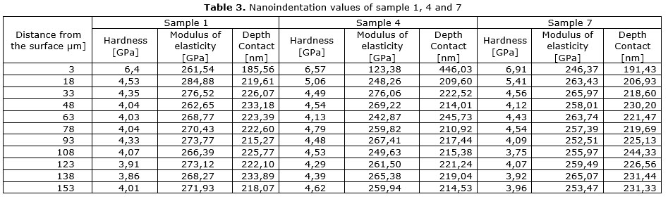
The nanoindentation was performed to samples belonging to the test specimens 1, 4 and 7 which were machined with a feedrate of 0,01 mm / rev and cutting speeds of 100, 451 and 722 m / min respectively. These samples presented the higher values of mechanical deformationaccording to the higher compressive stresses measured.
The samples were cut in small pieces (dimensions 20x8x8 mm), mounted in resin to facilitate the subsequent polishment and attack with a solution of Nital at2%.
The nanoindentation tests were performed in a Nanoindenter G200 (MTS) system DCM, with a maximum load of 5 mN. Indentation was performed using a diamond indenter point type Berkovich, with a loading time of 15 s and a retention time of 10s. For the data processing the method of Oliver and Pharr was used.
55 indentations measurements were performed using an arrangement of (11 x 5) along the cross section of eachmachined-surface sample, with a separation of 15µm between indentations and 3 µm from edge.
Metallography
Some of the samples were observed with the use SEM techniques, to resolve the microstructure in the deformed zone and to determine the superficial and sub-superficial deformation forms.
RESULTS AND DISCUSSION
Surface Roughness Measurement
The curves of the surface roughness behavior in relation to the variation of cutting speed and feed rate are shown in figure 3 and figure 4 respectively.
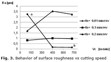
Analyzing the results presented in figure 3, it is observed that for cutting speeds above 451 m/min and small feed rates (between 0,01 and 0,1 mm/rev), increases on cutting speed has little influence on surface roughness , but for higher feed rate values, a distinct behavior is observed. As it is presented in the mentioned figure, for a feed rate of 0,2 mm/rev, there is a tendency to reduce surface roughness as cutting speed increases. This behavior coincides particularly with those obtained by Jacobson [1], Rech [13] and in general with those presented by Devillez [14], Asiltürk [3] and Aouici [5].
For values of cutting speeds below 451 m/min and a feed rate of 0,2 mm/rev, it is observed a large increase in surface roughness while cutting speed is increased, this trend also holds for a feed rate of 0,1 mm/rev, but with a less steep slope. For a not usual feed rate of 0,01 mm/rev, surface roughness highly decreases with increasing cutting speeds. Such behavior has not been reported in the literature yet, possibly due to cutting conditions bordering extremely low feed rate with high cutting speeds.
An example of very high surface roughness that can be obtained with feed rates of 0,01 mm/rev and low cutting speeds is the point identified by the letter (a) in figure 3, with a cutting speed of 100m/min and a feed rate of 0,01 mm/rev, presents a very high roughness value (3,25 µm). According to Rech [13], low feed rates produce a plastic flow of the material in the direction opposite to the direction of feed rate. Burrs are formed on the edges of the grooves left by the tool. Also the increase of the temperature causes the solder of particles of the machined material to the work piece surface. It was also observed, in addition to the above Rech [13], the influence of the low-rate material removal produced by the low values of cutting speeds and feed rates, which implies a large amount of generated heat that is not removed along with the chip and gets transmitted to the machined part, increasing thus its temperature. This is confirmed by the results of Richardson [15].
A point (b) has also been identified in figure 3 for the highest cutting speed and the lowest feed rate.
In figure 4, one can observe that the values of surface roughness for cutting speeds of 451 m/min and 722 m/min are very similar for all the feed rates tested.

For both cutting speeds, surface roughness increases as feed rate does. It may also be noted that for feed rates higher than 0,1 mm/rev an increment of feed rate implies an increase in surface roughness for all cutting speeds. This agrees with several reported results in literature [3-5, 13, 14]. However, for a cutting speed of 100 m/min the behavior is different for feed rates below 0,1 mm/rev. The graph shows an increment of surface roughness as the feed rate decreases from a value of 0,1 mm/rev. A plausible explanation for this phenomenon was given in the paragraphs above based in the results of Rech [13].
In figure 5 the relief some of the machined surfaces are shown. Two samples have been selected for this analysis, minimum (a) and maximum cutting speed (b) with the minimum feed rate. One can observe the high level of deformation produced on both surfaces.
Measurement of residual stresses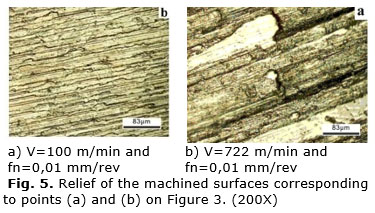
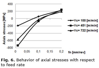
Figure 6 shows the variation of axial stresses with respect to feed rate and figure 7, shows the behavior of the circumferential stresses with respect to cutting speed.
In figure 6 it is observed that for a feed rate of 0,01 mm /rev, and for any value of cutting speed, the values of axial residual stresses in the work piece-surface are compressive. However, increases in the values of feed rate tend to transform residual stresses from the compression to the traction range. For the higher cutting speeds this occurs above 0,1 mm/rev, although for a cutting speed of 100 m/min the tensile stresses appears at lower feed rate values. It can be also pointed out, that for all the values of cutting speeds, the lines representing the change of the stresses from compression to traction show a slope change at 0,1 mm/rev, becoming less steep for values above it. This behavior fully coincides with the affirmed by [8, 9, 11].
In figure 7, for feed rates of 0,1 and 0,2 mm/rev, it is observed that with increasing cutting speed in the range
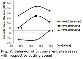
(100-451 m/min), the circumferential residual stresses rise in the direction of traction and above 451 m/min, the direction of the residual stresses tends to be reversed in the direction of compression, which coincides with results reported in literature [8-11, 13]. For an extremely low feed rate of 0,01 mm/rev, the prevalence of compressive residual stresses indicates that the mechanical deformations produced, predominate over the thermal deformation, generating compression stresses. At a cutting speed of 722 m/min, these compressive stresses show a large reduction (point a), reaching similar values to point (b). This can be explained if we compare the rate of material removal (RMR) of point (a) and (b) in figure 8, which are 3610 mm3/min, and 5000 mm3/min respectively. Comparing the values shown in figure 8 these two values can be considered as nearby values and could explain the similarity in stresses.

Nano hardness measurements
Table 3 shows the average values of hardness, modulus of elasticity, and depth of contact.
The graph presented in figure 9, shows that the maximum hardness values are found in the surface and are in the range of 6,4 to 6,9 GPa, showing a slight increase with increasing cutting speed (sample 1- 100m/min; sample 2- 451m/min; sample 7- 722m/min). The hardness values decrease as the distance from the surface increases up to 50 µm. For higher distances, the hardness values show a nearly uniform behavior with most of the values in the range of 4 to 4,5 GPa. These results agree with those obtained by [8- 9].

Samples were subjected to metallographic examination by a scanning electronic microscope. Two distinctive zones of plastic deformation were observed in the ferrite - perlite structure (See Fig. 10): A large deformation zone (a), exactly beneath the surface, with a thickness of about 1-3 µm, and a lower deformation area (b) with a thickness of approximately 7-12 µm., coinciding these results with those obtained in [12].

Limitations of the work
Is the wish of the authors to go deeper into the nano-hardness measurement and in the metallography analysis. In both cases only 3 samples were used due to equipment availability. In the partiality of this analysis resides the main limitation of the research.
CONCLUSION
After the tests performed to determine the influence of cutting speed and feedrate on surface integrity of the 1045 steel the following conclusions were reached:
1. For cutting speeds above 451 m /min and small feed rates (in the range 0,01 and 0,1 mm / rev), increased cutting speed has little influence on the surface roughness, observing a distinct behavior at a higher feedrate value,(0,2 mm/rev), where there is a tendency to reduce surface roughness with an increase in cutting speed.
2. With an increase of the feed rate from 0,01 to 0,2 mm /rev, the axial residual stresses tend to change from compressive stresses and move to tensile stresses.With increasing cutting speeds from 100 to 451m /min, using feed rates in the range of 0,1to 0,2 mm / rev, the circumferential residual stress rises in the direction of traction, reversing the direction to compression with increases of the cutting speed above 451m/ min.For an extremely low feedrate (0,01 mm / rev) and any of the tested cutting speed, residual stresses were compressive.
3. The nano hardness measurements in the surface layer of samples subjected to compressive stresses, ie with a high mechanical deformation, reached values of maximum hardness near the surface of the sample in the range from 6,4 to 6,9 GPa. These maximum values were decreasing up to 4 – 4,5GPa at a depth below the surface of approximately 50μm.
4. The samples subjected to metallographic analysis showed two deformation zones: a large deformation zone (1-3 µm thickness) and a minor deformation zone (7-12 µm).
ACKNOWLEDGEMENTS
The authors wish to express their gratitude to CAPES for the funding provided for this research.
The authors express their sincere thanks to Dra. Lavinia María Sanábio Alves Borges, coordinator of project CAPES-MES 125/11, of Federal University of Rio Janeiro.
REFERENCES
1. Jacobson M. Cutting speed influence on surface integrity of hard turned bainite steel. Journal of Materials Processing Technology. 2002;128:318-23. ISSN 0924-0136.
2. Bouacha K. Statistical analysis of surface roughness and cutting forces using response surface methodology in hard turning of AISI 52100 bearing steel with CBN tool. International Journal of Refractory Metals & Hard Materials. 2010;28:349–61. ISSN 0263-4368.
3. Asilturk I. Determining the effect of cutting parameters on surface roughness in hard turning using the Taguchi method. Measurement. 2011;44:1697–704. ISSN 0263-2241.
4. Bordin A, Bruschi S, Ghiotti A. The effect of cutting speed and feed rate on the surface integrity in dry turning of CoCrMo alloy. Procedia CIRP. 2014;13:219-24. ISSN 2212-8271. DOI 10.1016/j.procir.2014.04.038.
5. Aouici H. Analysis of surface roughness and cutting force components in hard turning with CBN tool: Prediction model and cutting conditions optimization. Measurement. 2012;45:344-53. ISSN 0263-2241.
6. Axinte DA, Dewes RC. Surface integrity of hot work tool steel after high speed milling experimental data and empirical models. Journal of Materials Processing Technology. 2002;127:325–35. ISSN 0924-0136.
7. Gunnberg F. The influence of cutting parameters on residual stresses and surface topography during hard turning of 18 MnCr5 case carburised steel. Journal of Materials Processing Technology. 2006;174:82-90. ISSN 0924-0136.
8. Pawade R. Effect of machining parameters and cutting edge geometry on surface integrity of high-speed turned Inconel 718. International Journal of Machine Tools & Manufacture. 2008;48:15-28. ISSN 0890-6955.
9. Sharman A. An analysis of the residual stresses generated in Inconel 718TM when turning. Journal of Materials Processing Technology. 2006;173:359–67. ISSN 0924-0136.
10. Caruso S. An experimental investigation of residual stresses in hard machining of AISI 52100 steel. Procedia Engineering. 2011;19:67-72. ISSN 1877-7058.
11. García V. Effect of cutting parameters in the surface residual stresses generated by turning in AISI 4340 steel. International Journal of Machine Tools & Manufacture. 2012;61:48-57. ISSN 0890-6955.
12. Puerta J. Sub-surface and surface analysis of high speed machined Ti–6Al–4V alloy. Materials Science and Engineering. 2010;527:2572–8. ISSN 0921-5093.
13. Rech J. Surface integrity in finish hard turning of case-hardened steels. International Journal of Machine Tools & Manufacture. 2003;43:543–50. ISSN 0890-6955.
14. Devillez A. Dry machining of Inconel 718, workpiece surface integrity. Journal of Materials Processing Technology. 2011;211:1590-8. ISSN 0924-0136.
15. Richardson DJ. Modelling of cutting induced workpiece temperatures for dry Milling. International Journal of Machine Tools & Manufacture. 2006;46:1139-45. ISSN 0890-6955.
Received: 3 de mayo de 2015.
Accepted: 5 de julio de 2015.
Mario Jacas-Cabrera. Instituto Superior Politécnico José Antonio Echeverría, Facultad de Ingeniería Mecánica. La Habana, Cuba
E-mail: jacas@mecanica.cujae.edu.cu

