


My SciELO
 Custom services
Services on Demand
Article
 English (pdf)
 Article in xml format
 Article references
 Send this article by e-mail
Indicators
-
 Cited by SciELO
Related links
-
 Similars in
SciELO
Similars in
SciELO
Share

 Permalink
Minería y Geología
On-line version ISSN 1993-8012
Min. Geol. vol.33 no.1 Moa Jan.-Mar. 2017
ARTÍCULO ORIGINAL
Monitoring of flank wear and damage in high-speed end milling inclined surfaces of hardened steel AISI D6
Supervisión del desgaste y deterioro de flancos en fresado extremo de alta velocidade en superficies inclinadas de acero endurecido AISI D6
Yanier Sánchez Hechavarría1, Maritza Mariño Cala1, Luis Ángel Brito Sauvanell1, Frank Sanabria Macías1
1Universidad de Oriente. Santiago de Cuba. Cuba rysan@uo.edu.cu
Abstract
Cutting tool condition monitoring system in the industry is mainly used to detect tool wear, breakage and chatter on the tool. In this paper, tool wear with two inclination surfaces angles was investigated in end milling inclined surface using cutting force signals. This study is focused in the time domain radial force amplitude analysis and Root Mean Square (RMS) values for tool wear monitoring in milling process. The RMS value of the radial cutting force is increased with the flank wear and inclination angle increases. The analysis of the RMS values of the radial cutting force can be effectively used for the tool wear progression monitoring during milling operations. It was confirmed that in end milling inclined surface the predominant mechanism of damage is adhesive–abrasive.
Keywords: milling; monitoring; inclined surfaces; wear; mechanism of damage; cutting force.
Resumen
Los sistemas de monitoreo de las condiciones de la herramienta de corte son principalmente usados en la industria para detectar desgaste, rotura y vibraciones auto-excitadas. En este artículo se investiga el desgaste de la herramienta en el proceso de fresado de superficies inclinadas, con dos ángulos de inclinación, usando las señales de fuerza de corte. Este estudio se enfoca en el monitoreo del desgaste en el proceso de fresado a través del análisis de la amplitud de la señal de fuerza radial en el dominio del tiempo y los valores de la Raíz Media Cuadrática (RMS). Se determinó que los valores de RMS se incrementan con el aumento del desgaste de flanco y el ángulo de inclinación de la superficie. Los valores de RMS de la fuerza de corte radial son usados efectivamente para el monitoreo de la progresión del desgaste de la herramienta durante operaciones de fresado. Se confirmó, además, que el mecanismo de desgaste de la herramienta de corte en el proceso de fresado de superficies inclinadas es predominantemente adhesivo–abrasivo.
Palabras clave: fresado; superficies inclinadas; monitoreo; desgaste; mecanismos de desgaste; fuerza de corte.
1. INTRODUCTION
In manufacturing industries milling is generally used to produce parts which are not axially symmetric and have many features such as holes, slots, pockets and three dimensional surfaces contours. This process is capable of producing machine elements with complex shapes and high surface quality, such as molds and dies, gears, shafts, blades, etc. The productivity of machining processes, as well as the integrity of the machined surface are strongly related to the tool wear and tool life. Tool wear, hence, becomes the key factor in the machining processes. If a worn tool is not identified beforehand, significant degradation of the workpiece quality can occur. Therefore, research in this area is still of great significance (Jozić, Bajic and Topic 2012).
1.1. Tool wear
Three causes of damage are qualitatively identified: mechanical, thermal and adhesive. Mechanical damage, which includes abrasion, chipping, early fracture and fatigue, is basically independent of temperature. Thermal damage, with plastic deformation, thermal diffusion and chemical reaction as its typical forms, increases drastically with increasing temperature (It should be noted that thermal diffusion and chemical reaction are not the direct cause of damage. Rather, they cause the tool surface to be weakened so that abrasion, mechanical shock or adhesion can then more easily cause material removal). Damage based on adhesion is observed to have a local maximum in a certain temperature range (Childs et al. 2000).
Wear is a loss of material on an asperity or micro-contact, or smaller scale, down to molecular or atomic removal mechanisms. It usually progresses continuously. Tribological processes leading to tool wear occur at rake and flank face, as shown in Figure 1 (Childs et al. 2000; Grote and Atonsons 2009).
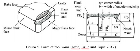
Flank wear is caused by friction between the flank face of the tool and the machined workpiece surface and leads to loss of the cutting edge. Therefore, flank wear affects the dimensional accuracy and surface finish quality. In practice, flank wear is generally used as the tool wear criteria (Jozić, Bajic and Topic 2012).
Criteria for the selection of the tool’s end of life has to consider that the operations were carried out under a finish, where the fundamental requirement is to get a good surface finish and dimensional tolerances. For these operations flank wear VB should not exceed 0,2 mm for IT7 qualities and grades of 0,3 mm to IT8 (Diniz, Marcondes and Coppini 2010).
During milling process, the cutting edges periodically enter and exit the workpiece. Hence, it experiences stress and temperature cycling during cutting. This periodic coupled mechanical-thermal cycle produces alternating compression and tensile stresses on the tool that may exceed its strength. Even if the thermal stress amplitudes are not large enough to break the tool instantly, the thermal stress cycling causes gradual fatigue failure and wear of the tool. The temperature is a direct function of the relative speed and friction force between the materials in contact. Higher speeds result in more friction energy, which increases the temperature at the contact zone between the workpiece and the tool. As the flank wear increases, the tool workpiece contact area increases too (Altintas 2012; Jozić, Lela and Batić 2014).
1.2. Monitoring of the tool condition
Hence, tool wear becomes the key factor in the machining processes. If a worn tool is not identified previously, significant degradation of the workpiece quality can occur. Therefore, research in this area is of great significance. Several methods have been proposed to monitoring tool wear. There are two main categories: direct and indirect methods. With direct methods, it is possible to measure tool wear directly using some optical instrument such as video camera, which requires cutting operations to be interrupted periodically. Various indirect methods for tool condition monitoring (TCM) are used by modeling the correlation between tool wear and sensory signals, namely, the cutting force, torque, current, power, vibration, and acoustic emission acquired in machining processes (Sivasakthivel, Velmurugan and Sudhakaran 2010; Antić et al. 2013).
Kwon and Fischer (2003) have developed the tool wear index (TWI) and the tool life model, analyzing the wear surface areas and the tool material loss by means of micro optics, image processing, and an analysis algorithm. With relation to surface roughness, the TWI measures the minimum risk for in-process tool failure, and it is integrated in an optimal control strategy according to criteria of productivity improvement and reduction of manufacturing cost.
Özel and other researchers (2009)have investigated the influence of cutting parameters on the tool flank wear and surface roughness in hard steel finish turning. Crater and flank wear of ceramic tool are observed with scanning electron microscopy (SEM) after corresponding runs. Linear regression and neural network models are developed for the prediction of tool flank wear and surface roughness. Lajis et al. (2008) have performed similar modeling methodology and measuring techniques in end milling of hardened steel.
1.3. Metallurgical Fundamentals
Hardness working steels, mainly applied in the tool and die making, allow the generation of a homogeneous and isotropic material microstructure. They are characterized by a high hardness, ductility, and pressure strength and possess a good dimensional stability during their heat treatment. Depending on the specific alloy composition and the heat treatment, the hardness can be varied between 50 and 70 HRC. Therefore, the high hardness of these materials can be reached by carbide precipitation and martensitic transformation (Tonshoff, Arendt and Ben-Amor 2000). Precipitation hardening, for instance, leads to an improvement of the stability of the workpieces under static and especially pulsatory loads. This leads to a considerably enhanced property profile compared to conventional die materials. Hence, the lifetime of forming tools can be improved drastically (Klocke et al. 2011).
Furthermore, powder metallurgical steels can be customized referring to the specific area of application with respect to their hardness, heat, and wear resistance or ductility. For instance, the method of spray-compacting permits the adjustment of an extreme wear resistant microstructure due to the high amount of embedded carbides (Piotrowiak et al. 2004; Klocke et al. 2011).
1.4. Milling inclined surfaces
During ball end milling of inclined surfaces, the inclination angle of the machined surface is variable, which affects the active length of cutting edge and working angle values. Consequently, this phenomenon influences cutting forces (Kitan, Kadhim and Abdulrazzaq 2011; Wojciechowski, Twardowski and Pelic 2014), and vibrations generated during machining process. From the literature survey it is also resulting, that surface inclination angle affects surface roughness (Vopát, Peterka and Kováč 2014), and the tool wear (Wojciechowski, Twardowski and Pelic 2014), during ball end milling. Therefore, the reliable prediction of milling forces including surface inclination is significant for the simulation of the machinability, cutter wear, vibrations, as well as the surface quality.
Varying the angle of the milled surface produces a change in the value of the radial and axial components of the cutting force. An increase of the inclination angle of the surface causes an increase in the radial component of the cutting force and decreases the axial component. As the radial direction is a little rigid, a higher angle inclination of the milled surface causes greater vibrations and decreasing of tool life (Campa, López De Lacalle and Celaya 2011).
Tüysuz (2012) established that during finish milling of inclined surfaces, the displacements of the tool resulting from the action of the cutting force induce perpendicular vibrations to the axis of rotation of the tool and parallel vibrations to the advance vector. In addition, the radial force component produces perpendicular displacements to axis of rotation of the tool and to the advance vector.
During the milling of inclined surfaces, the tool end of life criteria must be established from the determination of the flank wear, as it is the predominant wear type. (Vopát, Peterka and Kováč 2014) determined that ininclined surfaces milling the central wear is not verified, due to the fact that tool center has no contact with the piece, and this interaction is between the minimum effective diameter and the maximum effective diameter.
With the increasing of the radial component of the cutting force due to the low stiffness of the tool in this direction, an increase of the vibrations is produced and provokes dynamic instabilities and a decrease in tool life (Tüysuz 2012).
The purpose of this paper is to monitor the tool wear process during milling of inclined surfaces of hardened steel for cold work AISI D6 from the analysis the Root Mean Square (RMS) value of the radial cutting force. We also establish the flank wear progression and mechanisms that characterizes it.
2. EXPERIMENTAL METHOD
2.1 Equipment
The experiments were performed in a 3-axis CNC vertical machining center MORI SEIKI SV 40 with 22 kW of power in the spindle motor and a maximum tool rotation of 12 000 r/min. Cemented tungsten carbide inserts with coated TiAlN, were used for the milling tests. These inserts are manufactured by SANDVIK COROMANT, their reference was R216F-16 40 E-L P10A and the tool holder reference was R216F-16A16C-063. The milling tool was changed after to obtain a maximum wear value.
Tool wear evolution during the tests was monitored using a QUIMIS stereomicroscope with 100X maximum magnification and MOTIC IMAGES PLUS 2.0 ML software. The end of the tool life was determined by a maximum flank wear (VBBmax) of 0,2 mm. During the test, the flank wear was measured at 100 passing of the tool on the workpiece.
After concluding the tests, the tools, were examined in a scanning electron microscope (SEM) JEOL JXA-840A, which provides higher magnification and has an energy dispersive X-ray spectrometer (EDS) resource that allows chemical elements to be identified and then facilitates wear mechanisms to be establish or at least deduced.
A KISTLER 9257BA stationary dynamometer, a National Instruments PCI-6025E analogical/digital data acquisition board and LabVIEW 8.5 software were used for 3-axis cutting force (FX, FY and FZ) measurements. The signals were processed with MatLab 2015 software. Cutting forces were measured before starting the tool wear tests, establishing its initial value and the magnitude of cutting force signals is obtained from RMS value.
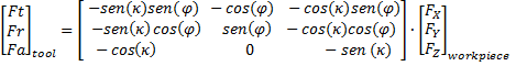
In inclined milling surfaces, the tangential, radial and axial components of the cutting force on the tool, Ft, Fr and Fa, respectively, are functions of instantaneous angle (φ) in the feed direction and the axial immersion angle (κ), and can be obtained by:
 (1)
(1)
When the cutting forces were measured while cutting a workpiece fixed onto the dynamometer, the components measured were parallel to the three axes of the machine tool (FX, FY and FZ) and, for our purposes, it was interesting to have the Ft, Fr and Fa component.
2.2. Workpiece material
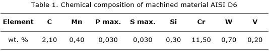
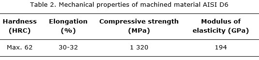
The selected workpiece material was hardened cold-work tool steel AISI D6, with an approximate hardness of 62 HRC. AISI D6 tool steel is a high-carbon, high chromium tool steel alloyed with tungsten that is characterized by high compressive strength, high wear resistance, high surface hardness and good hardening stability. Chemical composition and mechanical properties are shown in Tables 1 and 2.
Two workpieces were manufactured with dimensions of 265x215x125 mm and with inclinations of the surface to mechanize of 45º and 75º. The kinematics representation of movements of ball nose end mill was implemented in machining of the workpiece.
A free form surface can be milled using the horizontal downward strategy with two inclination angles. Both cases of ramping are shown in Figure 2.

2.3. Cutting conditions
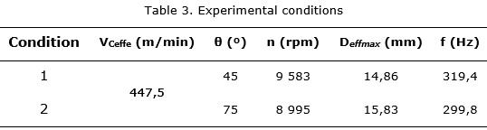
All wear tests were carried out with the following parameters: axial depth of cut ap=0,15 mm, radial depth of cut ae=0,15 mm, feed per tooth fz=0,15 mm/tooth. Experimental conditions are shows in Table 3.
Cutting speeds were selected in order to achieve the same value of cutting speed of the spindle 45° and 75° in two of the experimental conditions. The experiments were replicated 3 times to set the value of force and from which the tool reaches the maximum wear criteria, enabling the determination of the wear mechanism that produces the tool wear at the contact point between the tool and the workpiece.
3. RESULTS AND DISCUSSION
Through off-line tools wear measurements, it could be confirmed that the dominant wear during milling of inclined surfaces hardened steel AISI D6 is located on the cutting tool flank (Figures 3 y 4). Following, the new tool (VB=0 mm), slightly worn tool (VB≈0,140 mm), and severely worn tool (VB≥0,2 mm) are shown.

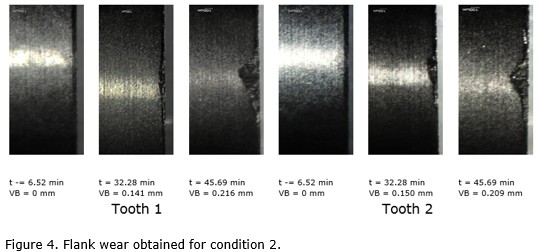
In Figure 3, it can be observed that the tools used in the experimental condition 1 the wear of the two teeth of the mill is almost the same, but did not happen in the experimental condition 2 (Figure 4), which shows that the middle wear point has a variation of 9 mm in the tooth 1 with respect to the tooth 2, this difference is reduced at the end of life of the tool to 6 mm. This is associated with a higher cutting tool radial deflection produced by the increase of the radial force due to the increase of the inclination of the milled surface (De Oliveira 2007). The arguments of this author allows to say that, through on-line monitoring of the radial component of the cutting force can predict progression of the process of flank wear of the cutting tool till reach the end of life criteria and to determine the mechanisms that will produce flank wear.
3.1. Monitoring flank wear through the analysis of the RMS of the radial cutting force
The raw signals of the cutting forces in three axis are analyzed in time domain as showed in Figure 5. The time domain is plot different cutting forces which are tangential cutting force (Ft), radial cutting force (Fr), and axial cutting force (Fa). This figure shows that the axial cutting force (Fa) is higher than Ft and Fr during the end milling process.
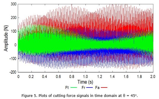
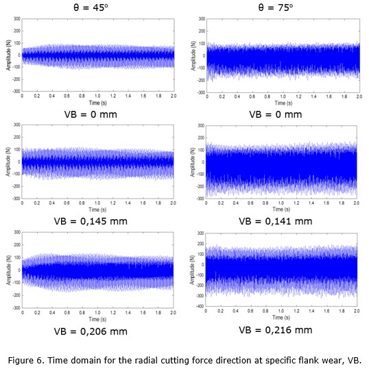
Figure 6 presents the radial cutting force in time domain for both inclination angles of the milling surface, for the specific flank wear values. Based on the Figures 3 and 4, the amplitude of the radial cutting force signals is increased with the flank wear increasing, until the criteria VB=0,2 mm is reached. It clearly shows that the tool flank wear caused the radial cutting force increase. Besides that, the increasing of inclination angle (θ) also makes the signal amplitude increased.
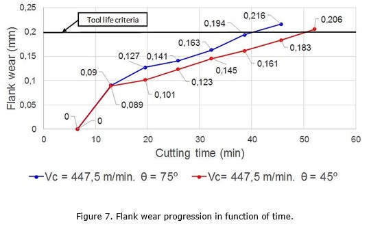
To set RMS values near to the criteria of lifetime ending, tool wear progression versus time curve was made (Figure 7). Taking into account this, RMS values near to maximum wear were determined to carry out on-line monitoring and set as calibration values 25,15 for experimental condition 1 and 36,07 for experimental condition 2. Calibration values are colored in red (Table 4).
Figure 7 clearly shows that the tool used during inclined surface milling with 75° (condition 2) reached first the end of life criteria than the tool used during milling inclined surface with 45º (condition 1), a point that as discussed previously, is associated with the increase of the radial cutting force component.
Sánchez and other researchers (2016) proved that the increasing of the inclination angle of the milled surface from 45° to 75° produces an increase in RMS of the radial and tangential components of cutting force, this indicates that the vibrations which are generated during milling inclined surfaces are affected by the variation of the inclination of the milled surface. In Figure 8, the curve of variation of RMS value against the progression of flank wear of the tool is shown. This figure shows that the RMS value of the radial force signal increases with the increasing flank wear, observing also that the RMS values for the experimental condition 2 are higher than for the experimental condition 1 in all cases.
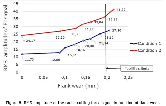
The values of RMS of radial force signal and flank wear measurement for each set of experiments are also presented in Table 4. Based on this table, the values RMS are increased with the tool wear and cutting time increasing.
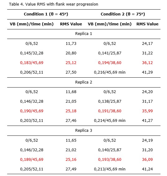
The increasing of the value of RMS is due to the widening of the contact of surface area between the work piece and the tool, so a larger value of RMS is produced due to the increase of the radial force amplitude. This is the same that has been established by previous studies in which a RMS value indicates an increase of the tangential and radial cutting force and vice versa (Sánchez et al. 2016). The results shown in Table 4 allow monitoring the wear process of the cutting tool and predict time wear criteria of tool during the milling process of inclined surfaces.
In front end milling processes, the increase of the radial force causes radial deflection of the tool that induces a biggest gap between the consecutive passes of the teeth causing the appearance of regenerative vibrations due to the chatter phenomena, which is related to the appearance of dynamic instabilities.
3.2. Wear mechanisms
A microanalysis using Scanning Electron Microscopy (SEM) and an energy dispersive X-ray spectrometer (EDS) was performed on the coated tool in two conditions. In Figure 9, it can be seen that during milling of the condition 1, appear fissures evidencing abrasive wear and cracks in the central area of wear. In this condition the values of RMS of the radial force signal are lowers, indicating that the process of milling inclined surface is dynamically more stable. The presence of tungsten in the wear area is due to the presence of this material in the core of the tool, the coating is lost. The presence of titanium in the periphery of the worn area may indicate that there is still coating material in that area. These cracks are caused by the increased value of the radial force that produces the radial deflections of the tool.

In Figure 10, the results of SEM and EDS for condition 2 are shown. In this condition, the values of the RMS are higher indicating the dynamical instabilities. In this figure, it can be observed that in the area where there was maximum flank wear, there is tungsten presence and iron adhesion due to the exposure of the tool core. The presence of titanium in the periphery of the worn area may indicate that there is coating material in that area, similar to condition 1.
In the worn area (Figure 10) cracks appear in the material flow direction making evident the presence of abrasive wear. Abrasive wear observed for this condition is caused by the movement of hard particles that are coming from the tool and the workpiece that are detach due to the high frequency of teeth input and the abrasive wear mechanism, higher than in all previous cases, criteria that have coincidence with Diniz, Marcondes and Coppini (2010). All this points permit to confirm the presence of a combined adhesive abrasive wear mechanism.

4. CONCLUSIONS
After analyzing the results, we can conclude that:
1. In the end milling process of inclined surfaces of the cold working hardened steel AISI D6, the predominant wear occurs in the flank surface of the tool and it is directly associated to the increase of the radial cutting force and forced vibrations .
2. When the inclination angle (θ) of the milled surface is increased, the amplitude of the cutting force in time domain is higher and the value of RMS is rising too.
3. It was proven that in radial cutting force signals, the proposed method gives satisfactory results for monitoring tool flank wear changes during the end milling process of inclined surfaces.
4. In end milling processes of inclined surfaces hardened cold working steel AISI D6, with angles of 45° and 75°, the wear predominant mechanism is adhesive–abrasive.
5. REFERENCES
Antić, A.; Šimunović, G.; Šarić, T.; Milošević, M. and Ficko, M. 2013: A model of tool wear monitoring system for turning. Tehnicki Vjesnik 20(2): 247–254. Consulted: 10 Sept 2016. Available in: https://www.researchgate.net/publication/285539042_A_model_of_tool_wear_monitoring
Altintas, Y. 2012: Manufacturing automation: metal cutting mechanics, machine tool vibrations, and CNC design. Second Edition. Cambridge University, New York.
Campa, F. J.; López De Lacalle, L. N. and Celaya, A. 2011: Chatter avoidance in the milling of thin floors with bull-nose end mills: Model and stability diagrams. International Journal of Machine Tools and Manufacture 51: 43-53. Consulted: 29 Oct 2016. Available in: http://fulltext.study/preview/pdf/784497.pdf
Childs, T.; Maekawa, K.; Obikawa, T. and Yamane, Y. 2000: Metal Machining. Theory and Applications. First Edition. Hodder Headline Group, London.
De Oliveira, A. J. 2007: Análise do desgaste de ferramentas no ferramentas no Fresamento com Alta Velocidade de aços endurecidos. Doctoral thesis. Universidade Estadual de Campinas. Brasil. Consulted: 30 Oct 2016. Available in: http://www.bibliotecadigital.unicamp.br/document/?code=vtls000415721
Diniz, A. E.; Marcondes, F. C. and Coppini, N. L. 2010: Tecnologia da usinagem dos metais. Sétima edição. Editora Artileber Ltda, São Paulo.
Grote, K. H. and Atonsons, E. K. 2009: Handbook of mechanical engineering. Springer, New York.
Jozić, S.; Bajic, D. and Topic, S. 2012: Flank wear in down and up milling. Proceedings of the 23rd International DAAAM Symposium 23(1): 0251-0254. Consulted: 1 Sept 2016. Available in: http://www.daaam.info/Downloads/Pdfs/proceedings/proceedings_2012/0251_Jozicatal.pdf
Jozić, S.; Lela, B. and Batić, D. 2014: A New Mathematical Model for Flank Wear Prediction Using Functional Data Analysis Methodology. Hindawi Publishing Corporation. Advances in Materials Science and Engineering 2014 (ID 138168): 2-8. Consulted: 12 Sept 2016. Available in: https://www.hindawi.com/journals/amse/2014/138168/abs/
Kitan, H. S.; Kadhim, B. I. and Abdulrazzaq, S. A. 2011: Cutting Forces Prediction in Ball End Milling. Engineering and Technology Journal 29(9): 1774-1789. Consulted: 27 Feb 2016.
Klocke, F.; Arntz, K.; Cabral, G. F.; Stolorz, M. and Busch. M. 2011: Characterization of tool wear in high-speed milling of hardened powder metallurgical steels. Hindawi Publishing Corporation Advances in Tribology 2011 (ID 90648): 2-13. Consulted: 23 Oct 2016. Available in: https://www.hindawi.com/journals/at/2011/906481/
Kwon, Y. and Fischer, G. W. 2003: A novel approach to quantifying tool wear and tool life measurements for optimal tool management. International Journal of Machine Tools and Manufacture 43(4): 359–368. Consulted: 28 Jan 2016. Available in: https://www.researchgate.net/publication/245096213_A_novel_approach_to_quantifying_tool_
wear_and_tool_life_measurements_for_optimal_tool_management
Lajis, M. A.; Karim, A. N. M.; Amin, A. K. M. N.; Hafiz, A. M. K. and Turnad, L. G. 2008: Prediction of tool life in end milling of hardened steel AISI D2. European Journal of Scientific Research 21(4): 592–602. Consulted: 10 Sept 2016. Available in: http://irep.iium.edu.my/26853/1/TL_Mill_D2_%238.pdf
Özel, T.; Karpat, Y.; Figueira, L. and Davim, J. P. 2009: Modeling of surface finish and tool wear in hard turning of AISI D2 steel using ceramics wiper inserts. Journal of Materials Processing Technology. 209: 5448–5455. Consulted: 11 March 2016. Available in: https://pdfs.semanticscholar.org/186f/21eae72eb48efeae1be2ea840d3438126c37.pdf
Piotrowiak, R.; Schuler, V.; Schruff, I. and Spiegelhauer, C. 2004: Spruhkompaktierte Hochleistungs-Werkzeugstahle. HTM Zeitschrift fur Werkstoffe, Warmebehandlung und Fertigung 59(6): 423–431. Consulted: 27 Oct 2016. Available in: http://www.hanser-elibrary.com/doi/pdf/10.3139/105.100315
Sánchez, Y.; Diniz, A. E.; Mariño, M. and Sanabria, F. 2016: Influencia del material del portaherramientas en la estabilidad dinámica del fresado de acero endurecido AISI D6. Revista Iberoamericana de Ingeniería Mecánica 20(1): 73-85.
Sivasakthivel, P. S.; Velmurugan, V. and Sudhakaran, R. 2010: Prediction of vibration amplitude from machining parameters by response surface methodology in end milling. International Journal of Advanced Manufacturing Technology 2: 1780–1789. Consulted: 23 Nov 2016. Available in: https://www.researchgate.net/publication/50281790_Prediction_of_tool_wear_from_machining_
parameters_by_response_surface_methodology_in_end_milling
Tonshoff, H. K.; Arendt, C. and Ben-Amor R. 2000: Cutting of hardened steel. Annals of the CIRP 49(2): 547–566. Consulted: 3 Sept 2016. Available in: https://www.researchgate.net/publication/229136898_Cutting_of_Hardened_Steel
Tüysuz, O. 2012: Prediction of cutting forces in three and five-axis ball-end milling with tool indentation effect. Master's Thesis. The University of British Columbia. Vancouver, Canada. Consulted: 3 Sept 2016. Available in: https://open.library.ubc.ca/media/download/pdf/24/1.0072530/2/565
Vopát, T.; Peterka, J. and Kováč, M. 2014: The tool life of ball nose end mill depending on the different types of ramping. Slovak University of Technology in Bratislava 22(Special Number): 115–121. Consulted: 1 Sept 2016. Available in: http://www.mtf.stuba.sk/docs/doc/casopis_Vedecke_prace/33SN/4-Vopat.pdf
Wojciechowski, S.; Twardowski, P. and Pelic, M. 2014: Cutting forces and vibrations during ball end milling of inclined surfaces. 6th CIRP International Conference on High Performance Cutting HPC 2014. PROCEDIA CIRP 14: 113-118. Consulted: 12 April 2016. Available in: https://www.researchgate.net/publication/263049465_Cutting_Forces_and_Vibrations_During_Ball
_End_Milling_of_Inclined_Surfaces
Recibido: 10/10/2016
Aceptado: 10/11/2016
Yanier Sánchez Hechavarría, Máster en Procesos de Manufactura y Materiales. Profesor Auxiliar. Universidad de Oriente. Santiago de Cuba. Cuba rysan@uo.edu.cu

